This SDL diagram example was redesigned from the Wikimedia Commons file: Sdl beispiel client.png. [commons.wikimedia.org/ wiki/ File:Sdl_ beispiel_ client.png]
This file is licensed under the Creative Commons Attribution-Share Alike 3.0 Unported license. [creativecommons.org/ licenses/ by-sa/ 3.0/ deed.en]
The diagram "Specification and Description Language example" was created using the ConceptDraw PRO diagramming and vector drawing software extended with the Specification and Description Language (SDL) solution from the Engineering area of ConceptDraw Solution Park.
SDL diagram example
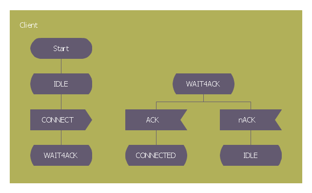
 Specification and Description Language (SDL)
For people in the field of systems engineering or system design, working with specification and description language (sdl) and finite state machines (fsm).
SDL — Systems Engineering

FSM — Finite-state Machine

Finite State Machine

SDL Flowchart Symbols

System Design

Types of Flowcharts


Detail Specifications Exchanging Mind Maps with Evernote

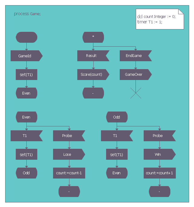
SDL Diagram

This sample shows the SDL Diagram of the process game.
Model Based Systems Engineering

This SDL diagram example was redesigned from the Wikimedia Commons file: SDL processGame.png.
"Diagram of the process Game in SDL (Specification and Description Language)." [commons.wikimedia.org/ wiki/ File:SDL_ processGame.png]
This file is made available under the Creative Commons CC0 1.0 Universal Public Domain Dedication. [creativecommons.org/ publicdomain/ zero/ 1.0/ deed.en]
The diagram example "SDL process Game" was created using the ConceptDraw PRO diagramming and vector drawing software extended with the Specification and Description Language (SDL) solution from the Engineering area of ConceptDraw Solution Park.
SDL diagram exampe
Diagramming Software for Design UML Interaction Overview Diagrams


Fault Tree Analysis Example

- Specification and Description Language example | Specification and ...
- Specification and Description Language (SDL) | SDL — Systems ...
- SDL — Systems Engineering | Specification and Description ...
- Specification and Description Language (SDL) | SDL — Systems ...
- SDL — Systems Engineering | Specification and Description ...
- Finite State Machine | Specification and Description Language (SDL ...
- Languages of South America - Thematic map | Specification and ...
- How to Create a SDL Diagram Using ConceptDraw PRO ...
- Specification and Description Language (SDL) | SDL Architecture ...
- Language Learning | Types of Flowcharts | Specification and ...
- Specification and Description Language (SDL) | Finite State ...
- Types of Flowcharts | Android GUI | Specification and Description ...
- Types of Flowcharts | Specification and Description Language (SDL ...
- FSM — Finite-state Machine | Finite State Machine | Specification ...
- Flowchart Description Language
- 3 Circle Venn. Venn Diagram Example | Specification and ...
- Process Flowchart | Specification and Description Language (SDL ...
- SDL Diagram | SDL — Systems Engineering | Specification and ...
- Specification and Description Language (SDL) | Plumbing and ...
- Specification and Description Language (SDL) | Personal area (PAN ...
- ERD | Entity Relationship Diagrams, ERD Software for Mac and Win
- Flowchart | Basic Flowchart Symbols and Meaning
- Flowchart | Flowchart Design - Symbols, Shapes, Stencils and Icons
- Flowchart | Flow Chart Symbols
- Electrical | Electrical Drawing - Wiring and Circuits Schematics
- Flowchart | Common Flowchart Symbols
- Flowchart | Common Flowchart Symbols