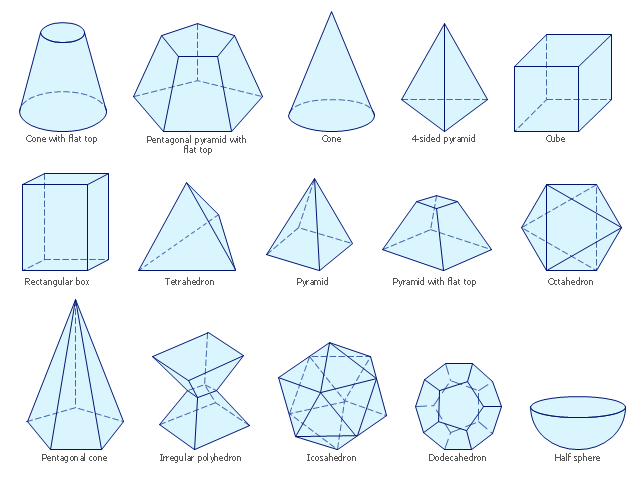
The vector stencils library "Solid geometry" contains 15 shapes of solid geometric figures.
"In mathematics, solid geometry was the traditional name for the geometry of three-dimensional Euclidean space - for practical purposes the kind of space we live in. It was developed following the development of plane geometry. Stereometry deals with the measurements of volumes of various solid figures including cylinder, circular cone, truncated cone, sphere, and prisms.
The Pythagoreans had dealt with the regular solids, but the pyramid, prism, cone and cylinder were not studied until the Platonists. Eudoxus established their measurement, proving the pyramid and cone to have one-third the volume of a prism and cylinder on the same base and of the same height, and was probably the discoverer of a proof that the volume of a sphere is proportional to the cube of its radius." [Solid geometry. Wikipedia]
The shapes example "Design elements - Solid geometry" was created using the ConceptDraw PRO diagramming and vector drawing software extended with the Mathematics solution from the Science and Education area of ConceptDraw Solution Park.
Solid geometrical figures
This example of automated teller machine (ATM) UML sequence diagram was created on the base of figure 5 "Sequence diagram" on the webpage "Message Sequence Charts and their Ilk" from the website of the University of California Irvine (UCI) Donald Bren School of Information and Computer Sciences.
"A UML sequence diagram or SD is similar to an MSC but written with a different notation. Presumably the same semantic issues arise, but possibly not since UML semantics are not well-defined. An example is shown in Figure 5.
The timelines are dotted rather than solid, and the name of the component is inside a box at the head of each timeline. The narrow rectangles apparently show when a component is active (unsure precisely what "active" means). An X on a timeline indicates that the component ceases to exist in some sense (unsure precisely how this is meant also). In the example, the Bank timeline has an X simply as an example (presumably the Bank does continue to exist)."
[www.ics.uci.edu/ ~alspaugh/ cls/ shr/ msc.html]
This example of bank ATM sequence diagram was created using the ConceptDraw PRO diagramming and vector drawing software extended with the ATM UML Diagrams solution from the Software Development area of ConceptDraw Solution Park.
Bank ATM UML sequence diagram

- Design elements - Solid geometry | Scientific Symbols Chart ...
- Plane Geometric Figures
- Butt weld geometry | Design elements - Solid geometry | Design ...
- ConceptDraw PRO: Able to Leap Tall Buildings in a Single Bound ...
- Basic Diagramming | How to Draw Geometric Shapes in ...
- Winter Olympics - Figure skating | People - Vector stencils library ...
- Flat House Design Examples
- Mathematics | Biology | Chemistry | Solution Science
- Scientific Symbols Chart | Block Diagrams | Design elements - Stars ...
- Object-Oriented Design | Booch OOD Diagram | Software ...
- Design elements - Greek letters
- Bio Flowchart Lite | Biology | Catabolism schematic - Biochemical ...
- Marketing mix - Wheel diagram
- How To use House Electrical Plan Software | Electrical Drawing ...
- Target Diagram
- Active Directory diagram - Site links | Computer network - Vector ...
- Circular Arrows Diagrams | Target and Circular Diagrams | How to ...
- Target and Circular Diagrams | Relative Circular Diagram | Circular ...
- Geo Map - USA - Washington | NTSB Training Center location | Geo ...
- Aerospace - Vector stencils library | CERES data flow diagram ...
- ERD | Entity Relationship Diagrams, ERD Software for Mac and Win
- Flowchart | Basic Flowchart Symbols and Meaning
- Flowchart | Flowchart Design - Symbols, Shapes, Stencils and Icons
- Flowchart | Flow Chart Symbols
- Electrical | Electrical Drawing - Wiring and Circuits Schematics
- Flowchart | Common Flowchart Symbols
- Flowchart | Common Flowchart Symbols