Activity Network Diagram Method

This sample shows the PERT (Program Evaluation Review Technique) chart of the request on proposal. A request for proposal (RFP) is a request of the company or the organization to potential suppliers to submit the business proposals for service or goods that it is interested to purchase. The RFP is represented on the initial procurement stage and allows to define the risks and benefits.
ConceptDraw PROJECT Software Overview

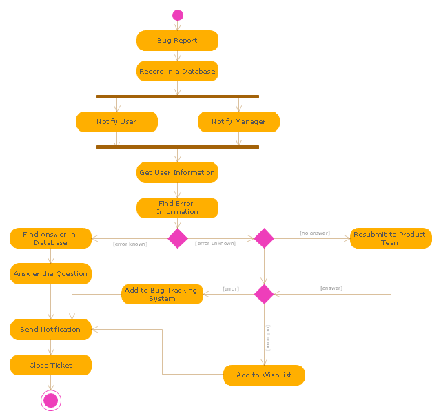
"An issue tracking system (also ITS, trouble ticket system, support ticket, request management or incident ticket system) is a computer software package that manages and maintains lists of issues, as needed by an organization. Issue tracking systems are commonly used in an organization's customer support call center to create, update, and resolve reported customer issues, or even issues reported by that organization's other employees. An issue tracking system often also contains a knowledge base containing information on each customer, resolutions to common problems, and other such data. An issue tracking system is similar to a "bugtracker", and often, a software company will sell both, and some bugtrackers are capable of being used as an issue tracking system, and vice versa. Consistent use of an issue or bug tracking system is considered one of the "hallmarks of a good software team".
A ticket element, within an issue tracking system, is a running report on a particular problem, its status, and other relevant data. They are commonly created in a help desk or call center environment and almost always have a unique reference number, also known as a case, issue or call log number which is used to allow the user or help staff to quickly locate, add to or communicate the status of the user's issue or request.
These tickets are so called because of their origin as small cards within a traditional wall mounted work planning system when this kind of support started. Operators or staff receiving a call or query from a user would fill out a small card with the user's details and a brief summary of the request and place it into a position (usually the last) in a column of pending slots for an appropriate engineer, so determining the staff member who would deal with the query and the priority of the request." [Issue tracking system. Wikipedia]
The UML activity diagram example "Ticket processing system" was created using the ConceptDraw PRO diagramming and vector drawing software extended with the Rapid UML solution from the Software Development area of ConceptDraw Solution Park.
UML activity diagram
"Request methods.
An HTTP 1.1 request made using telnet. The request, response headers and response body are highlighted.
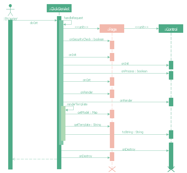
HTTP defines methods (sometimes referred to as verbs) to indicate the desired action to be performed on the identified resource. What this resource represents, whether pre-existing data or data that is generated dynamically, depends on the implementation of the server. Often, the resource corresponds to a file or the output of an executable residing on the server. The HTTP/ 1.0 specification:section 8 defined the GET, POST and HEAD methods and the HTTP/ 1.1 specification:section 9 added 5 new methods: OPTIONS, PUT, DELETE, TRACE and CONNECT. By being specified in these documents their semantics are well known and can be depended upon. Any client can use any method and the server can be configured to support any combination of methods. If a method is unknown to an intermediate it will be treated as an unsafe and non-idempotent method. There is no limit to the number of methods that can be defined and this allows for future methods to be specified without breaking existing infrastructure. For example, WebDAV defined 7 new methods and RFC5789 specified the PATCH method.
GET.
Requests a representation of the specified resource. Requests using GET should only retrieve data and should have no other effect. (This is also true of some other HTTP methods.)" [Hypertext Transfer Protocol. Wikipedia]
The UML sequence diagram example "GET request" was created using the ConceptDraw PRO diagramming and vector drawing software extended with the Rapid UML solution from the Software Development area of ConceptDraw Solution Park.
An HTTP 1.1 request made using telnet. The request, response headers and response body are highlighted.
HTTP defines methods (sometimes referred to as verbs) to indicate the desired action to be performed on the identified resource. What this resource represents, whether pre-existing data or data that is generated dynamically, depends on the implementation of the server. Often, the resource corresponds to a file or the output of an executable residing on the server. The HTTP/ 1.0 specification:section 8 defined the GET, POST and HEAD methods and the HTTP/ 1.1 specification:section 9 added 5 new methods: OPTIONS, PUT, DELETE, TRACE and CONNECT. By being specified in these documents their semantics are well known and can be depended upon. Any client can use any method and the server can be configured to support any combination of methods. If a method is unknown to an intermediate it will be treated as an unsafe and non-idempotent method. There is no limit to the number of methods that can be defined and this allows for future methods to be specified without breaking existing infrastructure. For example, WebDAV defined 7 new methods and RFC5789 specified the PATCH method.
GET.
Requests a representation of the specified resource. Requests using GET should only retrieve data and should have no other effect. (This is also true of some other HTTP methods.)" [Hypertext Transfer Protocol. Wikipedia]
The UML sequence diagram example "GET request" was created using the ConceptDraw PRO diagramming and vector drawing software extended with the Rapid UML solution from the Software Development area of ConceptDraw Solution Park.
UML sequence diagram
PERT Chart Software

ConceptDraw DIAGRAM is a powerful diagramming and vector drawing software for designing professional looking PERT Charts quick and easy.
Diagramming Software for designing UML Sequence Diagrams


Software Diagram Examples and Templates

Software Development area of ConceptDraw Solution Park provides 5 solutions:
Data Flow Diagrams, Entity-Relationship Diagram (ERD), Graphic User Interface, IDEFO Diagrams, Rapid UML.
Network Glossary Definition

Easy to draw network topology diagrams, network mapping and Cisco network topology.

PERT Chart

PERT Chart
Timeline Diagrams

ConceptDraw DIAGRAM extended with Timeline Diagrams solution from the Management area of ConceptDraw Solution Park is a powerful software for fast and easy drawing useful and great-looking timeline diagrams.
Best Value Stream Mapping mac Software

Purchasing Flowchart - Purchase Order. Flowchart Examples

The flow chart example shows the steps of purchasing business process.
The vector stencils library Alarm and access control contains 80 symbols of digital proximity equipment, locking hardware, and access control equipment.
"An alarm device or system of alarm devices gives an audible, visual or other form of alarm signal about a problem or condition. Alarm devices are often outfitted with a siren." [Alarm device. Wikipedia]
"An access control point, which can be a door, turnstile, parking gate, elevator, or other physical barrier, where granting access can be electronically controlled. Typically, the access point is a door. An electronic access control door can contain several elements. At its most basic, there is a stand-alone electric lock. The lock is unlocked by an operator with a switch. To automate this, operator intervention is replaced by a reader. The reader could be a keypad where a code is entered, it could be a card reader, or it could be a biometric reader. Readers do not usually make an access decision, but send a card number to an access control panel that verifies the number against an access list. To monitor the door position a magnetic door switch can be used. In concept, the door switch is not unlike those on refrigerators or car doors. Generally only entry is controlled, and exit is uncontrolled. In cases where exit is also controlled, a second reader is used on the opposite side of the door. In cases where exit is not controlled, free exit, a device called a request-to-exit (REX) is used. Request-to-exit devices can be a push-button or a motion detector. When the button is pushed, or the motion detector detects motion at the door, the door alarm is temporarily ignored while the door is opened. Exiting a door without having to electrically unlock the door is called mechanical free egress. This is an important safety feature. In cases where the lock must be electrically unlocked on exit, the request-to-exit device also unlocks the door." [Access control. Wikipedia]
Use the design elements library Alarm and access control for drawing layout floor plans, blueprints, and wiring diagrams of intrusion systems, time and attendance systems, card and code access control security systems, internal and external security control systems using the ConceptDraw PRO diagramming and vector drawing software.
The shapes library Alarm and access control is included in the Security and Access Plans solution from the Building Plans area of ConceptDraw Solution Park.
Alarm and access control symbols

Material Requisition Flowchart. Flowchart Examples

The flowchart example shows the material requisition business process.
Program Evaluation and Review Technique (PERT) with ConceptDraw DIAGRAM
 with ConceptDraw DIAGRAM *")
Check Order Process Flowchart. Flowchart Examples

This sample shows the Flowchart of the printing the elements of the binary search tree. They are printed in the order from lowest to greatest. On this diagram you can see the rectangles that represent the steps and decision points that are represented as diamonds with questions. It is necessary to make the decision that will determine the next step.
- Project timeline - Request for proposal plan | | Proposal Software ...
- UML sequence diagram - GET request | Rapid UML | Timeline ...
- UML sequence diagram - GET request | How to Get Images for ...
- Project plan timeline - Request for proposal (RFP) | Activity Network ...
- Process Flowchart | Amazon Web Services | Competing consumers ...
- Service Request Workflow Diagram
- PERT chart - Template | Seven Management and Planning Tools ...
- UML sequence diagram - GET request | UML sequence diagram ...
- UML sequence diagram - GET request | Design elements - Bank ...
- Timeline diagram - Project schedule | Project plan timeline ...
- Project plan timeline - Request for proposal (RFP) | Project Timeline ...
- Project plan timeline - Request for proposal (RFP) | Gantt charts for ...
- UML activity diagram - Ticket processing system | UML Activity ...
- UML sequence diagram - GET request | UML state machine diagram ...
- Sentence diagram - Compound predicate with one direct object ...
- Entity Relationship Diagram Examples | Drawing ER diagrams on a ...
- Structured Systems Analysis and Design Method. SSADM with ...
- Transition schematic - IDEF3 diagram example | Fishbone Diagram ...
- UML activity diagram - Ticket processing system | How to Create a ...
- Activity Network Diagram Method | PERT Chart Software | Activity on ...
- ERD | Entity Relationship Diagrams, ERD Software for Mac and Win
- Flowchart | Basic Flowchart Symbols and Meaning
- Flowchart | Flowchart Design - Symbols, Shapes, Stencils and Icons
- Flowchart | Flow Chart Symbols
- Electrical | Electrical Drawing - Wiring and Circuits Schematics
- Flowchart | Common Flowchart Symbols
- Flowchart | Common Flowchart Symbols