UML Activity Diagram

Use ConceptDraw PRO diagramming and vector drawing software enhanced with Rapid UML solution from ConceptDraw Solution Park to create your own UML activity diagrams that show the business and operational workflows of components and overall flow of control in your systems. Such software provides coloring UML diagrams for various purposes and simplifying work of the engineers.
Activity Network Diagram Method

This sample shows the PERT (Program Evaluation Review Technique) chart of the request on proposal. A request for proposal (RFP) is a request of the company or the organization to potential suppliers to submit the business proposals for service or goods that it is interested to purchase. The RFP is represented on the initial procurement stage and allows to define the risks and benefits.
UML Use Case Diagram Example Social Networking Sites Project

This sample shows the Facebook Socio-health system and is used at the projection and creating of the social networking sites.
HelpDesk
How to Organize a Social Media Activity
UML Diagram for System

UML Class Diagram Example - Social Networking Site

This sample shows the structure of the popular social networking site Linkedin and is used in the business field, in IT, at the projection and creating of the social networking sites.
 IDEF0 Diagrams
IDEF0 Diagrams visualize system models using the Integration Definition for Function Modeling (IDEF) methodology. Use them for analysis, development and integration of information and software systems, and business process modelling.
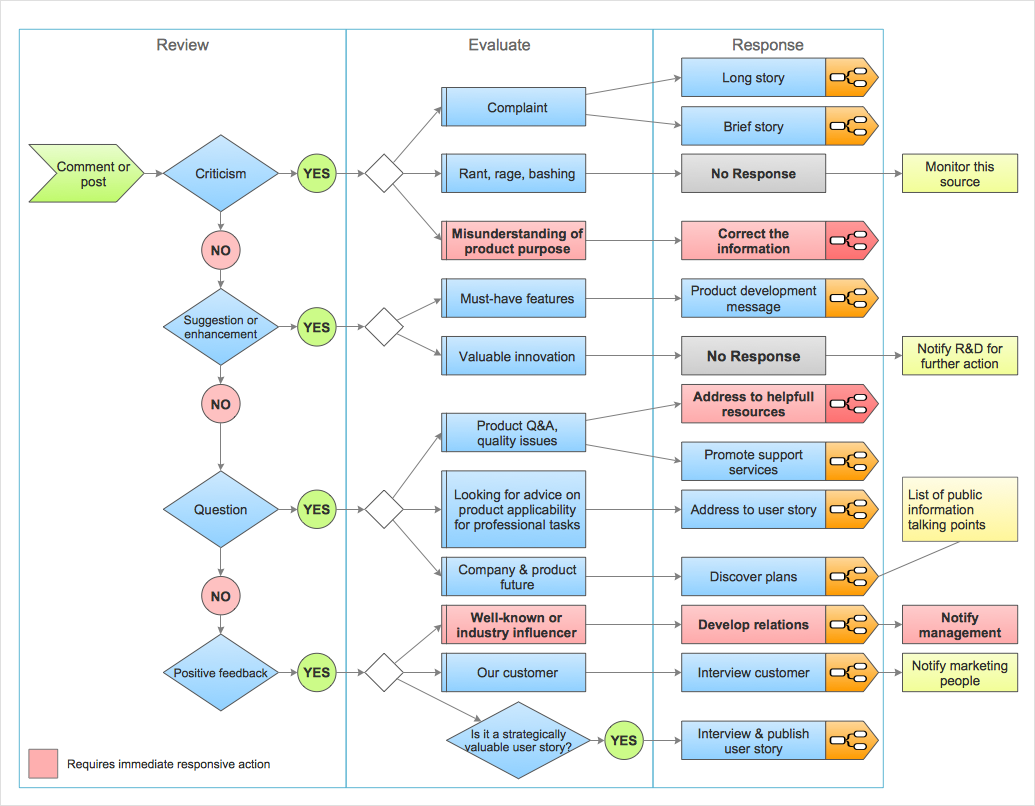
 Social Media Response
This solution extends ConceptDraw DIAGRAM and ConceptDraw MINDMAP with the ability to draw interactive flow charts with action mind map templates, to help create an effective response to applicable social media mentions.
UML Class Diagram Example - Buildings and Rooms

This sample shows the structure of the building and can be used by building companies, real estate agencies, at the buying / selling of the realty.
Activity on Node Network Diagramming Tool

This sample shows the Activity on node network diagramming method. It was created in ConceptDraw PRO diagramming and vector drawing software using the Seven Management and Planning Tools solution from the Management area of ConceptDraw Solution Park.
Organizing and Selecting Social Media Response Action

 Entity-Relationship Diagram (ERD)
An Entity-Relationship Diagram (ERD) is a visual presentation of entities and relationships. That type of diagrams is often used in the semi-structured or unstructured data in databases and information systems. At first glance ERD is similar to a flowch
Process Flowchart


UML Sample Project

- UML Activity Diagram | UML Class Diagram Example - Social ...
- Activity Diagram For Social Networking Project
- UML Activity Diagram | UML Use Case Diagram Example Social ...
- UML Deployment Diagram | UML Activity Diagram | UML Class ...
- UML Class Diagram Example - Social Networking Site | UML Activity ...
- For Website Draw Activity Diagram
- UML Activity Diagram | UML Use Case Diagram Example Social ...
- Activity Diagram For Facebook
- Activity Diagram For Social Network
- Activity Diagram For Real Estate Management
- Social Networking Site Activity Diagram
- UML Use Case Diagram Example Social Networking Sites Project ...
- Activity Diagram For Social Media
- UML activity diagram - Deposit slip processing | Cross-Functional ...
- UML Use Case Diagram Example Social Networking Sites Project ...
- UML activity diagram - Cash withdrawal from ATM | UML ...
- Activity Diagram For Facebook System
- Activity Diagram On Facebook
- Activity Diagram Facebook
- UML Sample Project | UML Use Case Diagram Example Social ...
- ERD | Entity Relationship Diagrams, ERD Software for Mac and Win
- Flowchart | Basic Flowchart Symbols and Meaning
- Flowchart | Flowchart Design - Symbols, Shapes, Stencils and Icons
- Flowchart | Flow Chart Symbols
- Electrical | Electrical Drawing - Wiring and Circuits Schematics
- Flowchart | Common Flowchart Symbols
- Flowchart | Common Flowchart Symbols