The vector stencils library "Process annotations" contains 22 symbols of interface points, slope, off-sheet labels, callouts and textboxes.
Use these shapes for setting automatic labels to display a datasheet field for a pipeline shape, labels, captions, outlines, off-sheet labels, text balloons, annotations, outlines, tags, and descriptions.
"In engineering a process is a set of interrelated tasks that, together, transform inputs into outputs. These tasks may be carried out by people, nature, or machines using resources; so an engineering process must be considered in the context of the agents carrying out the tasks, and the resource attributes involved. Systems Engineering normative documents and those related to Maturity Models are typically based on processes. For example, System Engineering processes of the EIA-632 and processes involved in the Capability Maturity Model Integration (CMMI) institutionalization and improvement approach. Constraints imposed on the tasks and resources required to implement them are essential for executing the tasks mentioned.
A chemical process is a series of unit operations used to produce a material in large quantities.
In the chemical industry, chemical engineers will use the following to define or illustrate a process:
Process Flow Diagram (PFD),
Piping and instrumentation diagram
(P&ID),
Simplified process description,
Detailed process description,
Project management,
Process simulation." [Process (engineering). Wikipedia]
The example "Design elements - Process annotations" was created using the ConceptDraw PRO diagramming and vector drawing software extended with the Chemical and Process Engineering solution from the Engineering area of ConceptDraw Solution Park.
Process annotation symbols

The vector stencils library "Dimensioning and tolerancing" contains 45 symbols of geometric dimensions and mechanical tolerances, geometric symbols, callouts, and text boxes and inserts.
Use these geometric dimensioning and tolerancing (GD&T) shapes to create annotated mechanical drawings in the ConceptDraw PRO diagramming and vector drawing software extended with the Mechanical Engineering solution from the Engineering area of ConceptDraw Solution Park.
www.conceptdraw.com/ solution-park/ engineering-mechanical
Datum (old)
-dimensioning-and-tolerancing---vector-stencils-library.png--diagram-flowchart-example.png)
Box callout

Datum symbol

Callout

All around callout

Text block

2 datum frame

Simple frame

Basic frame

1 datum frame

3 datum frame

Straightness

Flatness

Line profile

Circularity

Cylindricity

Surface profile

Position

Concentricity

Symmetry

Parallelism

Perpendicularity

Angularity

Material condition

Arc length

Diameter

Counterbore/ spotface

Countersink

Depth

Slope

Conical taper

Statistical tolerance

Datum (new)
-dimensioning-and-tolerancing---vector-stencils-library.png--diagram-flowchart-example.png)
Datum (new) 2
-2-dimensioning-and-tolerancing---vector-stencils-library.png--diagram-flowchart-example.png)
Target point

Target line

Target area (circle)
-dimensioning-and-tolerancing---vector-stencils-library.png--diagram-flowchart-example.png)
Target area (rectangle)
-dimensioning-and-tolerancing---vector-stencils-library.png--diagram-flowchart-example.png)
Total runout

Total runout 2

Circular runout

Circular runout 2

Surface finish

Surface finish, removal process

Surface finish, no process permitted

Garrett IA Diagrams with ConceptDraw PRO

This vector stencils library contains 22 symbols of process annotations for setting automatic labels to display a datasheet field for a pipeline shape, labels, captions, outlines, off-sheet labels, text balloons, annotations, outlines, tags, and descriptions.
Use these shapes for drawing Process Flow Diagrams (PFD) and Piping and Instrumentation Diagrams (P&ID) in the ConceptDraw PRO software extended with the Chemical and Process Engineering solution from the Chemical and Process Engineering area of ConceptDraw Solution Park.
www.conceptdraw.com/ solution-park/ engineering-chemical-process
Interface point

Interface point 2 (1st half filled)
-process-annotations---vector-stencils-library.png--diagram-flowchart-example.png)
Interface point 3 (2nd half filled)
-process-annotations---vector-stencils-library.png--diagram-flowchart-example.png)
Interface point 4

Interface point 5 (1st half filled)
-process-annotations---vector-stencils-library.png--diagram-flowchart-example.png)
Interface point 6 (2nd half filled)
-process-annotations---vector-stencils-library.png--diagram-flowchart-example.png)
Slope

Off-sheet label 1

Off-sheet label 2

Off-sheet label 3

Callout 1

Callout 2

Callout 3

Callout 4

Callout 5

Callout 6

8 pt text and line

10 pt text and line

12 pt text and line

12 pt Arial text block

10 pt Arial text block

8 pt Arial text block

 Mathematics
Mathematics solution extends ConceptDraw PRO software with templates, samples and libraries of vector stencils for drawing the mathematical illustrations, diagrams and charts.
Pyramid Diagram

 USA Maps
Use the USA Maps solution to create a map of USA, a US interstate map, printable US maps, US maps with cities and US maps with capitals. Create a complete USA states map.
Electrical Symbols — Analog and Digital Logic

26 libraries of the Electrical Engineering Solution of ConceptDraw PRO make your electrical diagramming simple, efficient, and effective. You can simply and quickly drop the ready-to-use objects from libraries into your document to create the electrical diagram.
Electrical Symbols — Switches and Relays

26 libraries of the Electrical Engineering Solution of ConceptDraw PRO make your electrical diagramming simple, efficient, and effective. You can simply and quickly drop the ready-to-use objects from libraries into your document to create the electrical diagram.
Process Flow Diagram Symbols

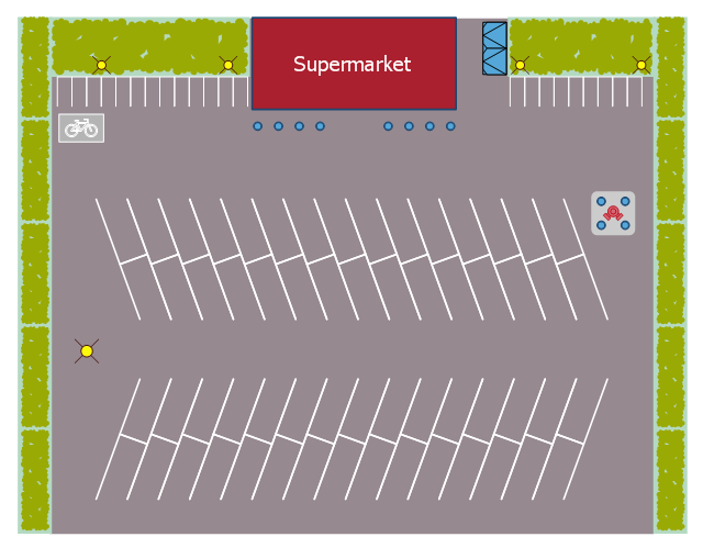
This landscape design sample depicts the supermarket parking site plan.
"Site planning in landscape architecture and architecture refers to the organizational stage of the landscape design process. It involves the organization of land use zoning, access, circulation, privacy, security, shelter, land drainage, and other factors. This is done by arranging the compositional elements of landform, planting, water, buildings and paving in site plans.
Site planning generally begins by assessing a potential site for development through site analysis. Information about slope, soils, hydrology, vegetation, parcel ownership, orientation, etc. are assessed and mapped. By determining areas that are poor for development (such as floodplain or steep slopes) and better for development, the planner or architect can assess optimal location and design a structure that works within this space." [Site planning. Wikipedia]
The site plan example "Supermarket parking" was created using the ConceptDraw PRO diagramming and vector drawing software extended with the Site Plans solution from the Building Plans area of ConceptDraw Solution Park.
Site plan
How To use House Electrical Plan Software

You can use many of built-in templates, electrical symbols and electical schemes examples of our House Electrical Diagram Software.
ConceptDraw is a fast way to draw: Electrical circuit diagrams, Schematics, Electrical Wiring, Circuit schematics, Digital circuits, Wiring in buildings, Electrical equipment, House electrical plans, Home cinema, Satellite television, Cable television, Closed-circuit television.
House Electrical Plan Software works across any platform, meaning you never have to worry about compatibility again. ConceptDraw PRO allows you to make electrical circuit diagrams on PC or macOS operating systems.

Electrical Symbols — Electrical Circuits

Electrical and electronic circuits can be complicated. Making a drawing of the connections to all the component parts in the circuit's load makes it easier to understand how circuit components are connected. Drawings for electronic circuits are called "circuit diagrams". Drawings for electrical circuits are called "wiring diagrams".
26 libraries of the Electrical Engineering Solution of ConceptDraw PRO make your electrical diagramming simple, efficient, and effective. You can simply and quickly drop the ready-to-use objects from libraries into your document to create the electrical diagram.
Electrical Symbols — Maintenance

The diagrams are a big help when workers try to find out why a circuit does not work correctly.
26 libraries of the Electrical Engineering Solution of ConceptDraw PRO make your electrical diagramming simple, efficient, and effective. You can simply and quickly drop the ready-to-use objects from libraries into your document to create the electrical diagram.
Value Stream Mapping Symbols

- Vector Tag Shape Png
- Vector Label Tag Png
- Logo Vegetation Png
- Callout Shapes Png
- Banner Shape Png
- Process Flowchart | Process Flow Diagram Symbols | Process and ...
- Balloon Callout Png
- Mechanical Drawing Symbols | Design elements - Chemical ...
- Half Circle Banners Png
- Label Png
- DroidDia PRO unlocker | DroidDia prime | Baseball Diagram ...
- Process Flowchart | Process Flow Diagram Symbols | Chemical and ...
- Chemical and Process Engineering | How to Draw a Chemical ...
- Flowchart design. Flowchart symbols , shapes, stencils and icons ...
- Potted Plant Png Plan
- Process Flowchart | Process Flow Diagram Symbols | Types of ...
- Mountain Vector Symbol Png
- Site Plans | Sport Field Plans | Site plan | Vegetation Plan
- Mechanical Drawing Symbols | Elements location of a welding ...
- Grass Plan Png
- ERD | Entity Relationship Diagrams, ERD Software for Mac and Win
- Flowchart | Basic Flowchart Symbols and Meaning
- Flowchart | Flowchart Design - Symbols, Shapes, Stencils and Icons
- Flowchart | Flow Chart Symbols
- Electrical | Electrical Drawing - Wiring and Circuits Schematics
- Flowchart | Common Flowchart Symbols
- Flowchart | Common Flowchart Symbols