Types of Flowcharts


 Specification and Description Language (SDL)
For people in the field of systems engineering or system design, working with specification and description language (sdl) and finite state machines (fsm).
Process Flowchart


SDL Diagram
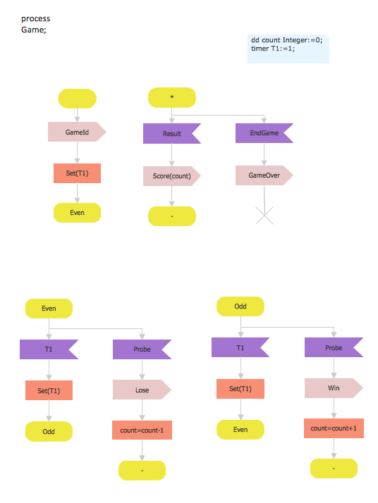
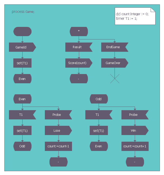
This sample shows the SDL Diagram of the process game.
HelpDesk
How to Create an SDL Diagram

SDL — Systems Engineering
System Design
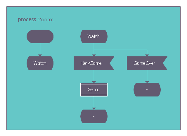
This SDL diagram example was redesigned from the Wikimedia Commons file: SDL processMonitor.png.
"Diagram of the process Monitor in SDL (Specification and Description Language)." [commons.wikimedia.org/ wiki/ File:SDL_ processMonitor.png]
This file is made available under the Creative Commons CC0 1.0 Universal Public Domain Dedication. [creativecommons.org/ publicdomain/ zero/ 1.0/ deed.en]
The diagram example "SDL process Monitor" was created using the ConceptDraw PRO diagramming and vector drawing software extended with the Specification and Description Language (SDL) solution from the Engineering area of ConceptDraw Solution Park.
SDL diagram example
This SDL diagram example was redesigned from the Wikimedia Commons file: SDL processGame.png.
"Diagram of the process Game in SDL (Specification and Description Language)." [commons.wikimedia.org/ wiki/ File:SDL_ processGame.png]
This file is made available under the Creative Commons CC0 1.0 Universal Public Domain Dedication. [creativecommons.org/ publicdomain/ zero/ 1.0/ deed.en]
The diagram example "SDL process Game" was created using the ConceptDraw PRO diagramming and vector drawing software extended with the Specification and Description Language (SDL) solution from the Engineering area of ConceptDraw Solution Park.
SDL diagram exampe
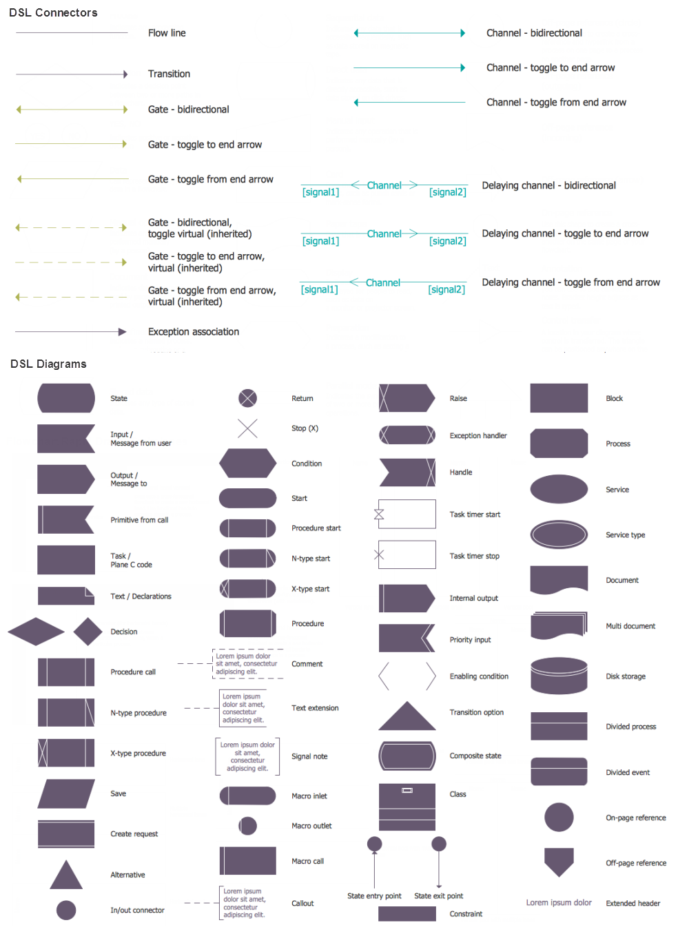
SDL Flowchart Symbols

Check Order Process Flowchart. Flowchart Examples
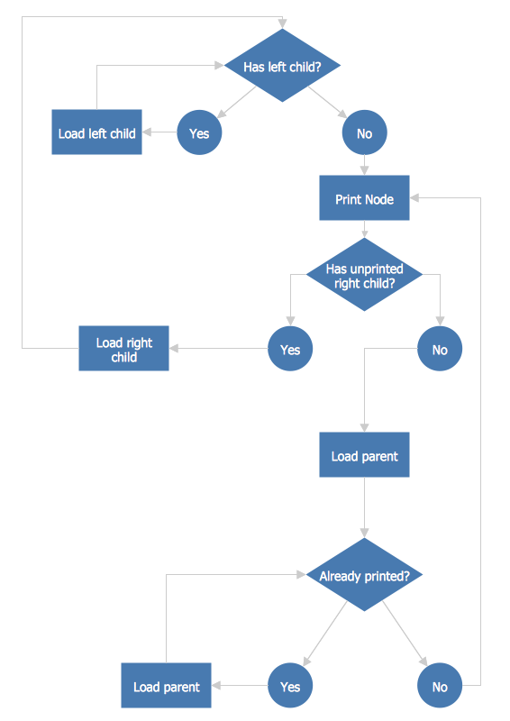
This sample shows the Flowchart of the printing the elements of the binary search tree. They are printed in the order from lowest to greatest. On this diagram you can see the rectangles that represent the steps and decision points that are represented as diamonds with questions. It is necessary to make the decision that will determine the next step.
ER Diagram for Cloud Computing

FSM — Finite-state Machine

Flowchart Software

ConceptDraw DIAGRAM flowchart software will help to quickly create new flowcharts, workflow, NS Diagram, BPMN Diagram, Cross-functional flowcharts, data flow diagrams and highlight flowcharts.
Feature-rich flowchart maker, free thousand flowchart examples and templates and colored symbols that will allow you to create professional looking flowcharts simply.
ConceptDraw DIAGRAM supports macOS and Windows.

- SDL Flowchart Symbols | SDL — Systems Engineering | Process ...
- Telecommunication Network Diagrams | Process Flowchart | SDL ...
- SDL Flowchart Symbols | Process Flowchart | Types of Flowcharts ...
- Basic Flowchart Symbols and Meaning | Process Flowchart | SDL ...
- Specification and Description Language ( SDL ) | Types of Flowcharts ...
- Process Flowchart | Types of Flowcharts | SDL Flowchart Symbols ...
- Process Flowchart | SDL Flowchart Symbols | Swim Lanes | Draw ...
- Process Flowchart | SDL Flowchart Symbols | How to Create an ...
- ER Diagram for Cloud Computing | SDL Diagram | Types of ...
- ER Diagram for Cloud Computing | SDL Diagram | Process ...
- Process Flowchart | Astronomy Symbols | SDL Flowchart Symbols ...
- Process Flowchart | Technical Flow Chart | SDL Flowchart Symbols ...
- SDL — Systems Engineering | Process Flowchart | System Design ...
- Process Flowchart | SDL Flowchart Symbols | Types of Flowcharts ...
- Process Flowchart | Making Mechanical Diagram | SDL Flowchart ...
- SDL Diagram | Specification and Description Language ( SDL ...
- SDL Flowchart Symbols | Process Flowchart | Design elements ...
- Specification and Description Language ( SDL ) | How to Create a ...
- Process Flowchart | Types of Flowcharts | Mechanical Design ...
- Process Flowchart | Circular Arrows Diagrams | Specification and ...
- ERD | Entity Relationship Diagrams, ERD Software for Mac and Win
- Flowchart | Basic Flowchart Symbols and Meaning
- Flowchart | Flowchart Design - Symbols, Shapes, Stencils and Icons
- Flowchart | Flow Chart Symbols
- Electrical | Electrical Drawing - Wiring and Circuits Schematics
- Flowchart | Common Flowchart Symbols
- Flowchart | Common Flowchart Symbols