 HVAC Plans
Use HVAC Plans solution to create professional, clear and vivid HVAC-systems design plans, which represent effectively your HVAC marketing plan ideas, develop plans for modern ventilation units, central air heaters, to display the refrigeration systems for automated buildings control, environmental control, and energy systems.
This reflected ceiling plan sample was created on the base of the article "How to Read a Reflected Ceiling Plan" from wikiHow.com.
"A reflected ceiling plan (RCP) is a drawing, which shows the items that are located on the ceiling of a room or space. It is referred to as a reflected ceiling plan since it is drawn to display a view of the ceiling as if it was reflected onto a mirror on the floor. This way the reflected ceiling plan has the same orientation as the floor plan associated with it. It is as if the ceiling was see-through and you could see right through it to the floor below. Architects and interior designers draw reflected ceiling plans when designing spaces." [wikihow.com/ Read-a-Reflected-Ceiling-Plan]
The HVAC layout example "RCP- HVAC layout" was created using the ConceptDraw DIAGRAM diagramming and vector drawing software extended with the Reflected Ceiling Plans solution from the Building Plans area of ConceptDraw Solution Park.
Reflected ceiling plan

HVAC Business Plan
HelpDesk
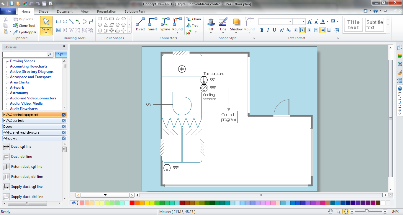
How to Create a HVAC Plan
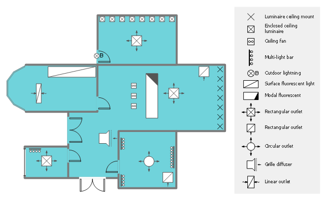
This reflected ceiling plan (RCP) sample shows lighting and HVAC layout.
"A "reflected ceiling plan" shows a view of the room as if looking from above, through the ceiling, at a mirror installed one foot below the ceiling level, which shows the reflected image of the ceiling above. This convention maintains the same orientation of the floor and ceilings plans - looking down from above. Reflected Ceiling Plans or RCP's are used by designers and architects to demonstrate lighting, visible mechanical features, and ceiling forms as part of the documents provided for construction." [Floor plan. Wikipedia]
The lighting and HVAC layout example "Reflected ceiling plan" was created using the ConceptDraw DIAGRAM diagramming and vector drawing software extended with the Reflected Ceiling Plans solution from the Building Plans area of ConceptDraw Solution Park.
Lighting and HVAC layout
HVAC Marketing Plan
This HVAC plan sample shows the air handler layout on the floor plan.
"An air handler, or air handling unit (often abbreviated to AHU), is a device used to condition and circulate air as part of a heating, ventilating, and air-conditioning (HVAC) system. An air handler is usually a large metal box containing a blower, heating or cooling elements, filter racks or chambers, sound attenuators, and dampers. Air handlers usually connect to a ductwork ventilation system that distributes the conditioned air through the building and returns it to the AHU. Sometimes AHUs discharge (supply) and admit (return) air directly to and from the space served without ductwork.
Small air handlers, for local use, are called terminal units, and may only include an air filter, coil, and blower; these simple terminal units are called blower coils or fan coil units. A larger air handler that conditions 100% outside air, and no recirculated air, is known as a makeup air unit (MAU). An air handler designed for outdoor use, typically on roofs, is known as a packaged unit (PU) or rooftop unit (RTU)." [Air handler. Wikipedia]
The floor plan example "Air handler - HVAC plan" was created using the ConceptDraw DIAGRAM diagramming and vector drawing software extended with the HVAC Plans solution from the Building Plans area of ConceptDraw Solution Park.
Floor plan

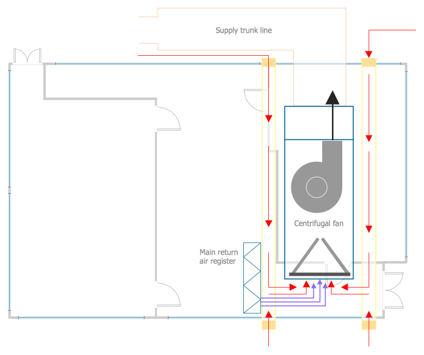
This mechanical room HVAC plan sample shows the layout of air handler (air handling unit, AHU) equipment: mixing chamber, air filter, fan (blower), heat exchanger coil, diffusers.
"Ventilating (the V in HVAC) is the process of "changing" or replacing air in any space to provide high indoor air quality (i.e. to control temperature, replenish oxygen, or remove moisture, odors, smoke, heat, dust, airborne bacteria, and carbon dioxide). Ventilation is used to remove unpleasant smells and excessive moisture, introduce outside air, to keep interior building air circulating, and to prevent stagnation of the interior air.
Ventilation includes both the exchange of air to the outside as well as circulation of air within the building. It is one of the most important factors for maintaining acceptable indoor air quality in buildings. Methods for ventilating a building may be divided into mechanical/ forced and natural types.
"Mechanical" or "forced" ventilation is used to control indoor air quality. Excess humidity, odors, and contaminants can often be controlled via dilution or replacement with outside air. However, in humid climates much energy is required to remove excess moisture from ventilation air.
Ventilation increases the energy needed for heating or cooling, however heat recovery ventilation can be used to mitigate the energy consumption. This involves heat exchange between incoming and outgoing air. Energy recovery ventilation additionally includes exchange of humidity." [Ventilation (architecture). Wikipedia]
The HVAC floor plan example "Ventilation system layout" was created using the ConceptDraw DIAGRAM diagramming and vector drawing software extended with the HVAC Plans solution from the Building Plans area of ConceptDraw Solution Park.
HVAC floor plan

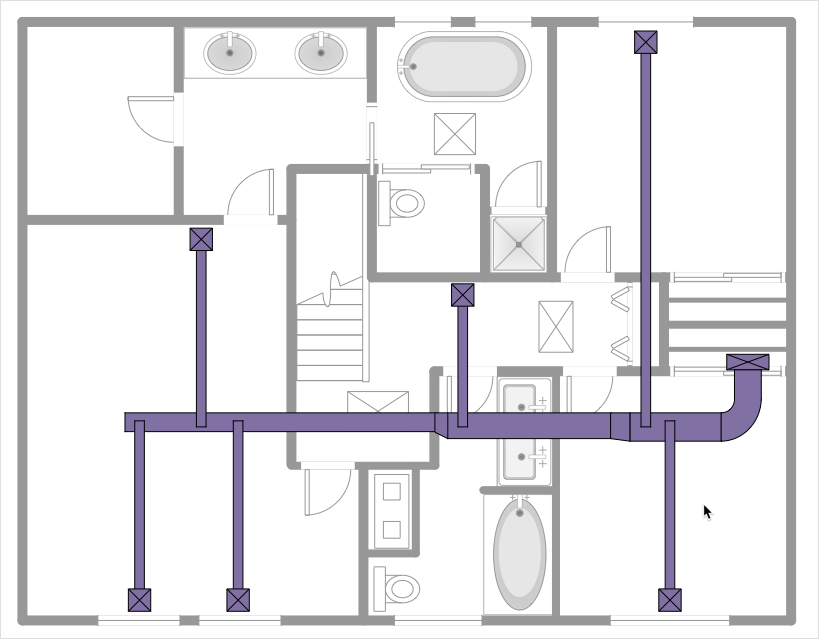
This HVAC floor plan sample shows the ventilation duct system layout.
"Ducts are used in heating, ventilation, and air conditioning (HVAC) to deliver and remove air. The needed airflows include, for example, supply air, return air, and exhaust air. Ducts commonly also deliver ventilation air as part of the supply air. As such, air ducts are one method of ensuring acceptable indoor air quality as well as thermal comfort.
A duct system is also called ductwork. Planning (laying out), sizing, optimizing, detailing, and finding the pressure losses through a duct system is called duct design." [Duct (flow). Wikipedia]
The HVAC floor plan example "Ductwork layout" was created using the ConceptDraw DIAGRAM diagramming and vector drawing software extended with the HVAC Plans solution from the Building Plans area of ConceptDraw Solution Park.
HVAC floor plan

Interior Design. Registers, Drills and Diffusers — Design Elements

 Cafe and Restaurant Floor Plans
Restaurants and cafes are popular places for recreation, relaxation, and are the scene for many impressions and memories, so their construction and design requires special attention. Restaurants must to be projected and constructed to be comfortable and e
 Plant Layout Plans
Plant Layout Plans solution can be used for power plant design and plant layout design, for making the needed building plant plans and plant layouts looking professionally good. Having the newest plant layout software, the plant design solutions and in particular the ConceptDraw’s Plant Layout Plans solution, including the pre-made templates, examples of the plant layout plans, and the stencil libraries with the design elements, the architects, electricians, interior designers, builders, telecommunications managers, plant design engineers, and other technicians can use them to create the professionally looking drawings within only a few minutes.
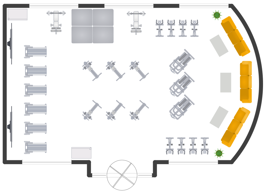
Gym Layout
Office Layout

You can use many of built-in templates and examples of our Office Layout Software. Start with the exact template you need then customize to fit your needs with more than 10000 stencils and you will find expected result in minutes.

- Hvac Layout Plan
- HVAC Plans | How to Create a HVAC Plan | Air handler- HVAC plan ...
- HVAC Plans | How to Create a HVAC Plan | HVAC Marketing Plan ...
- HVAC Plans | Block diagram - Automotive HVAC system | How to ...
- Reflected ceiling plan | RCP - HVAC layout | Studio space RCP ...
- HVAC Plans | Business diagrams & Org Charts with ConceptDraw ...
- RCP - HVAC layout | Reflected Ceiling Plan | Interior Design ...
- Hvac Floor Plans
- Lighting and switch layout | Reflected ceiling plan | Classroom ...
- Reflected Ceiling Plans | How to Create a Reflected Ceiling Floor ...
- Hvac Layout Of A Building
- Sample Of Floorplan For Networking
- RCP - HVAC layout | AWS Architecture Diagrams | Plumbing and ...
- How to Create a HVAC Plan | HVAC control equipment - Vector ...
- RCP - HVAC layout | How To use House Electrical Plan Software ...
- RCP - HVAC layout | How to Create a Reflected Ceiling Floor Plan ...
- Factory Floor Plans With Hvac Layout
- HVAC Plans | ConceptDraw Solution Park | Office Layout Plans ...
- How to Create a HVAC Plan | HVAC Plans | Air handler- HVAC plan ...
- HVAC Business Plan | Restaurant Floor Plans | HVAC Plans | How ...
- ERD | Entity Relationship Diagrams, ERD Software for Mac and Win
- Flowchart | Basic Flowchart Symbols and Meaning
- Flowchart | Flowchart Design - Symbols, Shapes, Stencils and Icons
- Flowchart | Flow Chart Symbols
- Electrical | Electrical Drawing - Wiring and Circuits Schematics
- Flowchart | Common Flowchart Symbols
- Flowchart | Common Flowchart Symbols