 ConceptDraw Solution Park
ConceptDraw Solution Park collects graphic extensions, examples and learning materials
HelpDesk
How to Draw a Chemical Process Flow Diagram

 Accounting Flowcharts
Accounting Flowcharts solution extends ConceptDraw DIAGRAM software with templates, samples and library of vector stencils for drawing the accounting flow charts.
HelpDesk
How to Draw a Process Flow Diagram

 Cross-Functional Flowcharts
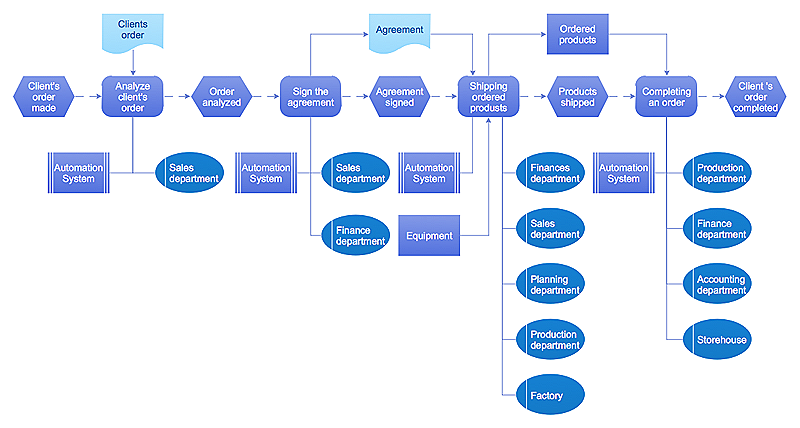
Cross-functional flowcharts are powerful and useful tool for visualizing and analyzing complex business processes which requires involvement of multiple people, teams or even departments. They let clearly represent a sequence of the process steps, the order of operations, relationships between processes and responsible functional units (such as departments or positions).
Business diagrams & Org Charts with ConceptDraw DIAGRAM


HelpDesk
How to Create a Sales Flowchart

 Sales Flowcharts
The Sales Flowcharts solution lets you create and display sales process maps, sales process workflows, sales steps, the sales process, and anything else involving sales process management.
 Chemical and Process Engineering
This chemical engineering solution extends ConceptDraw DIAGRAM.9.5 (or later) with process flow diagram symbols, samples, process diagrams templates and libraries of design elements for creating process and instrumentation diagrams, block flow diagrams (BFD
HelpDesk
How to Create a Data Flow Diagram

HelpDesk
Event-driven Process Chain (EPC) Diagram Software
An EPC diagram shows different business processes through various workflows. The workflows are seen as functions and events that are connected by different teams or people, as well as tasks that allow business processes to be executed. The best thing about this type of enterprise modeling is that creating an EPC diagram is quick and simple as long as you have the proper tool. One of the main usages of the EPC diagrams is in the modeling, analyzing and re-engineering of business processes. With the use of the flowchart, businesses are able to see inefficiencies in the processes and modify to make them more productive. Event-driven process chain diagrams are also used to configure an enterprise resource plan.
HelpDesk
How to Create Flowchart Using Standard Flowchart Symbols
- Sales Process Flowchart. Flowchart Examples | Accounting ...
- Sales Process Flowchart. Flowchart Examples | Marketing and Sales ...
- Sales Process Flowchart. Flowchart Examples | Process Flowchart ...
- Purchase Process Flow Chart. Accounting Flowchart Example ...
- Cross-Functional Flowcharts | Sales Process Flowchart. Flowchart ...
- Cross-Functional Flowcharts | Types of Flowchart - Overview ...
- Sales Process Flow Diagram
- Accounting Flowcharts | Cross-Functional Flowcharts | Sales ...
- Sales Process Flowchart. Flowchart Examples | Relations diagram ...
- Sales Process Flowchart. Flowchart Examples | How to Create a ...
- Sales Process Flowchart. Flowchart Examples
- Accounting Flowcharts | Purchase Process Flow Chart. Accounting ...
- Flowchart Software | Sales Process Flowchart. Flowchart Examples ...
- Flowchart Marketing Process . Flowchart Examples | Selecting ...
- Types of Flowchart - Overview | Flowcharts | Purchase Process Flow ...
- Cross-Functional Flowchart | Flowchart Software | Sales Process ...
- Cross-Functional Flowcharts | Accounting Flowcharts | Business ...
- Process Flowchart | Sales Process Flowchart. Flowchart Examples ...
- Basic Flowchart Symbols | Sales Process Flowchart. Flowchart ...
- DFD - Process of account receivable | Data Flow Diagram Process ...
- ERD | Entity Relationship Diagrams, ERD Software for Mac and Win
- Flowchart | Basic Flowchart Symbols and Meaning
- Flowchart | Flowchart Design - Symbols, Shapes, Stencils and Icons
- Flowchart | Flow Chart Symbols
- Electrical | Electrical Drawing - Wiring and Circuits Schematics
- Flowchart | Common Flowchart Symbols
- Flowchart | Common Flowchart Symbols