 Entity-Relationship Diagram (ERD)
Entity-Relationship Diagram (ERD) solution extends ConceptDraw PRO software with templates, samples and libraries of vector stencils from drawing the ER-diagrams by Chen's and crow’s foot notations.
ConceptDraw PRO Database Modeling Software

"An ER model is an abstract way of describing a database. In the case of a relational database, which stores data in tables, some of the data in these tables point to data in other tables - for instance, your entry in the database could point to several entries for each of the phone numbers that are yours. The ER model would say that you are an entity, and each phone number is an entity, and the relationship between you and the phone numbers is 'has a phone number'. Diagrams created to design these entities and relationships are called entity–relationship diagrams or ER diagrams.
Using the three schema approach to software engineering, there are three levels of ER models that may be developed. ...
Conceptual data model ... is the highest level ER model in that it contains the least granular detail but establishes the overall scope of what is to be included within the model set.
Logical ER model ... contains more detail than the conceptual ER model. In addition to master data entities, operational and transactional data entities are now defined.
The physical ER model is normally developed to be instantiated as a database. Therefore, each physical ER model must contain enough detail to produce a database and each physical ER model is technology dependent since each database management system is somewhat different.
Physical model ... is normally forward engineered to instantiate the structural metadata into a database management system as relational database objects such as database tables, database indexes such as unique key indexes, and database constraints such as a foreign key constraint or a commonality constraint." [Entity–relationship model. Wikipedia]
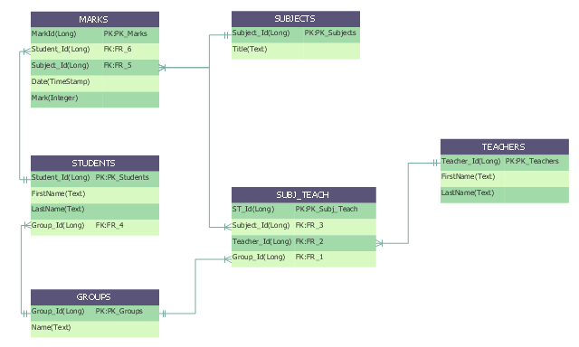
This crow's foot entity-relationship diagram (ERD) example "Educational data base" was created using the ConceptDraw PRO diagramming and vector drawing software extended with the Entity-Relationship Diagram (ERD) solution from the Software Development area of ConceptDraw Solution Park.
Using the three schema approach to software engineering, there are three levels of ER models that may be developed. ...
Conceptual data model ... is the highest level ER model in that it contains the least granular detail but establishes the overall scope of what is to be included within the model set.
Logical ER model ... contains more detail than the conceptual ER model. In addition to master data entities, operational and transactional data entities are now defined.
The physical ER model is normally developed to be instantiated as a database. Therefore, each physical ER model must contain enough detail to produce a database and each physical ER model is technology dependent since each database management system is somewhat different.
Physical model ... is normally forward engineered to instantiate the structural metadata into a database management system as relational database objects such as database tables, database indexes such as unique key indexes, and database constraints such as a foreign key constraint or a commonality constraint." [Entity–relationship model. Wikipedia]
This crow's foot entity-relationship diagram (ERD) example "Educational data base" was created using the ConceptDraw PRO diagramming and vector drawing software extended with the Entity-Relationship Diagram (ERD) solution from the Software Development area of ConceptDraw Solution Park.
ERD
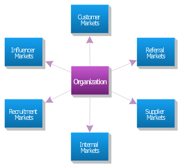
"The six markets model.
Christopher, Payne and Ballantyne (1991) from Cranfield University goes further. They identify six markets which they claim are central to relationship marketing. They are: internal markets, supplier markets, recruitment markets, referral markets, influence markets, and customer markets.
Referral marketing is developing and implementing a marketing plan to stimulate referrals. Although it may take months before you see the effect of referral marketing, this is often the most effective part of an overall marketing plan and the best use of resources.
Marketing to suppliers is aimed at ensuring a long-term conflict-free relationship in which all parties understand each other's needs and exceed each other's expectations. Such a strategy can reduce costs and improve quality.
Influence markets involve a wide range of sub-markets including: government regulators, standards bodies, lobbyists, stockholders, bankers, venture capitalists, financial analysts, stockbrokers, consumer associations, environmental associations, and labor associations. These activities are typically carried out by the public relations department, but relationship marketers feel that marketing to all six markets is the responsibility of everyone in the organization. Each market may require its own explicit strategies and a separate marketing mix for each." [Relationship marketing. Wikipedia]
The block diagram example "Six markets model" was created using the ConceptDraw PRO diagramming and vector drawing software extended with the Block Diagrams solution from the area "What is a Diagram" of ConceptDraw Solution Park.
Block diagram
"Crow's Foot notation is used in Barker's Notation, SSADM and Information Engineering. Crow's Foot diagrams represent entities as boxes, and relationships as lines between the boxes. Different shapes at the ends of these lines represent the cardinality of the relationship." [Entity–relationship model. Wikipedia]
The vector stencils library ERD, crow's foot notation contains 17 symbols for creating the ER-diagrams using the ConceptDraw PRO diagramming nd vector drawing software.
The example"Design elements - ERD solution (crow's foot notation)" is included in the Entity-Relationship Diagram (ERD) solution from the Software Development area of ConceptDraw Solution Park.
Crow's foot ERD
.png--diagram-flowchart-example.png)
- Design elements - ER diagram (Chen notation) | Design elements ...
- Design elements - ERD (crow's foot notation) | Entity Relationship ...
- Entity- Relationship Diagram (ERD) | ConceptDraw PRO ER ...
- ConceptDraw PRO Database Modeling Software | Entity ...
- Components of ER Diagram | Entity Relationship Diagram Symbols ...
- Business Models | Business model generation diagram | Business ...
- Business Process Modeling Software for Mac | Entity Relationship ...
- Entity- Relationship Diagram (ERD) with ConceptDraw PRO | Entity ...
- Entity- Relationship Diagram (ERD) | Fishbone Diagram ...
- Entity Relationship Diagram Chen Model
- Symbols Used In Entity Relation Models
- Venn diagram - Relationship marketing | Block diagram - Six ...
- Data Modeling with Entity Relationship Diagram
- Entity Relationship Diagram Data Model
- Entity Relationship Model Ssadm
- ERD Symbols and Meanings | Entity- Relationship Diagram (ERD ...
- Data Flow Diagram Symbols. DFD Library | Entity Relationship ...
- ConceptDraw PRO Database Modeling Software | Database ...
- Design elements - ER diagram (Chen notation) | Entity- Relationship ...
- Block diagram - Six markets model
- ERD | Entity Relationship Diagrams, ERD Software for Mac and Win
- Flowchart | Basic Flowchart Symbols and Meaning
- Flowchart | Flowchart Design - Symbols, Shapes, Stencils and Icons
- Flowchart | Flow Chart Symbols
- Electrical | Electrical Drawing - Wiring and Circuits Schematics
- Flowchart | Common Flowchart Symbols
- Flowchart | Common Flowchart Symbols