Electrical Symbols — Stations

26 libraries of the Electrical Engineering Solution of ConceptDraw DIAGRAM make your electrical diagramming simple, efficient, and effective. You can simply and quickly drop the ready-to-use objects from libraries into your document to create the electrical diagram.
Electrical Symbols — Transmission Paths
26 libraries of the Electrical Engineering Solution of ConceptDraw DIAGRAM make your electrical diagramming simple, efficient, and effective. You can simply and quickly drop the ready-to-use objects from libraries into your document to create the electrical diagram.
Electrical Symbols — VHF UHF SHF

26 libraries of the Electrical Engineering Solution of ConceptDraw DIAGRAM make your electrical diagramming simple, efficient, and effective. You can simply and quickly drop the ready-to-use objects from libraries into your document to create the electrical diagram.
The vector stencils library "VHF UHF SHF" contains 52 symbols for VHF, UHF, and SHF circuit design, including capacitance measurers, nonreciprocal devices, modulators, phase shifters, field polarization devices, and filters.
"Very high frequency (VHF) is the ITU-designated range of radio frequency electromagnetic waves from 30 MHz to 300 MHz, with corresponding wavelengths of one to ten meters. Frequencies immediately below VHF are denoted high frequency (HF), and the next higher frequencies are known as ultra high frequency (UHF).
Common uses for VHF are FM radio broadcasting, television broadcasting, land mobile stations (emergency, business, private use and military), long range data communication up to several tens of kilometres with radio modems, amateur radio, and marine communications. Air traffic control communications and air navigation systems (e.g. VOR, DME & ILS) work at distances of 100 kilometres or more to aircraft at cruising altitude.
VHF was previously used for analog television stations in the US." [Very high frequency. Wikipedia]
"Ultra-high frequency (UHF) designates the ITU radio frequency range of electromagnetic waves between 300 MHz and 3 GHz (3,000 MHz), also known as the decimetre band or decimetre wave as the wavelengths range from one to ten decimetres; that is 1 decimetre to 1 metre. Radio waves with frequencies above the UHF band fall into the SHF (super-high frequency) or microwave frequency range. Lower frequency signals fall into the VHF (very high frequency) or lower bands. UHF radio waves propagate mainly by line of sight; they are blocked by hills and large buildings although the transmission through building walls is high enough for indoor reception. They are used for television broadcasting (digital and analogue), cordless phones, walkie-talkies, satellite communication, and numerous other applications.
The IEEE defines the UHF radar band as frequencies between 300 MHz and 1 GHz. Two other IEEE radar band overlap the ITU UHF band: the L band between 1 and 2 GHz and the S band between 2 and 4 GHz." [Ultra high frequency. Wikipedia]
"Super high frequency (or SHF) is the ITU designation for radio frequencies (RF) in the range of 3 GHz and 30 GHz. This band of frequencies is also known as the centimetre band or centimetre wave as the wavelengths range from ten to one centimetres. These frequencies fall within the microwave band, so radio waves with these frequencies are called microwaves. The small wavelength of microwaves allows them to be directed in narrow beams by aperture antennas such as parabolic dishes, so they are used for point-to-point communication and data links, and for radar. This frequency range is used for most radar transmitters, microwave ovens, wireless LANs, cell phones, satellite communication, microwave radio relay links, and numerous short range terrestrial data links. The commencing wireless USB technology will be using approximately 1/ 3 of this spectrum.
Frequencies in the SHF range are often referred to by their IEEE radar band designations: S, C, X, Ku, K, or Ka band, or by similar NATO or EU designations." [Super high frequency. Wikipedia]
The shapes example "Design elements - VHF UHF SHF" was drawn using the ConceptDraw PRO diagramming and vector drawing software extended with the Electrical Engineering solution from the Engineering area of ConceptDraw Solution Park.
VHF, UHF, SHF symbols

Electrical Symbols — Qualifying

26 libraries of the Electrical Engineering Solution of ConceptDraw DIAGRAM make your electrical diagramming simple, efficient, and effective. You can simply and quickly drop the ready-to-use objects from libraries into your document to create the electrical diagram.
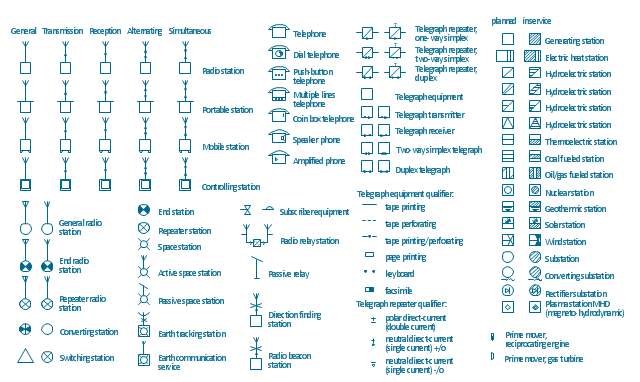
The vector stencils library "Stations" contains 110 symbols of communications equipment, generating, transmitting and receiving stations; substations; satellites; and power plants for power generation and distribution and radio relay systems.
"A power station (also referred to as a generating station, power plant, powerhouse or generating plant) is an industrial facility for the generation of electric power. At the center of nearly all power stations is a generator, a rotating machine that converts mechanical power into electrical power by creating relative motion between a magnetic field and a conductor. The energy source harnessed to turn the generator varies widely. It depends chiefly on which fuels are easily available, cheap enough and on the types of technology that the power company has access to. Most power stations in the world burn fossil fuels such as coal, oil, and natural gas to generate electricity, and some use nuclear power, but there is an increasing use of cleaner renewable sources such as solar, wind, wave and hydroelectric." [Power station. Wikipedia]
"Radio broadcasting is a one-way wireless transmission over radio waves intended to reach a wide audience. Stations can be linked in radio networks to broadcast a common radio format, either in broadcast syndication or simulcast or both. Audio broadcasting also can be done via cable radio, local wire television networks, satellite radio, and internet radio via streaming media on the Internet.
The signal types can be either analog audio or digital audio." [Radio broadcasting. Wikipedia]
The shapes example "Design elements - Stations" was drawn using the ConceptDraw PRO diagramming and vector drawing software extended with the Electrical Engineering solution from the Engineering area of ConceptDraw Solution Park.
Power and radio station symbols
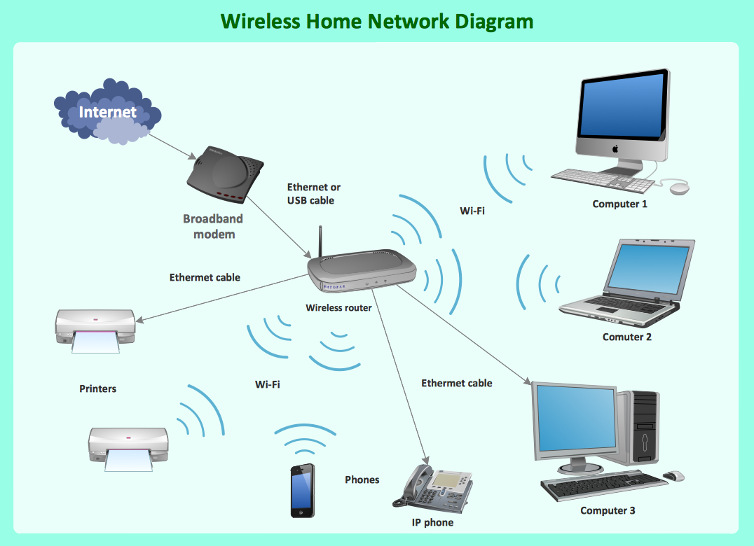
What Is a Wireless Network?
Electrical Symbols, Electrical Diagram Symbols

This solution provides 26 libraries which contain 926 electrical symbols from electrical engineering: Analog and Digital Logic, Composite Assemblies, Delay Elements, Electrical Circuits, Electron Tubes, IGFET, Inductors, Integrated Circuit, Lamps, Acoustics, Readouts, Logic Gate Diagram, MOSFET, Maintenance, Power Sources, Qualifying, Resistors, Rotating Equipment, Semiconductor Diodes, Semiconductors, Stations, Switches and Relays, Terminals and Connectors, Thermo, Transformers and Windings, Transistors, Transmission Paths,VHF UHF SHF.
The design elements library "Cable TV" contains 64 symbols of CATV network equipment.
"Cable television is a system of distributing television programs to subscribers via radio frequency (RF) signals transmitted through coaxial cables or light pulses through fiber-optic cables. This contrasts with traditional broadcast television (terrestrial television) in which the television signal is transmitted over the air by radio waves and received by a television antenna attached to the television. FM radio programming, high-speed Internet, telephone service, and similar non-television services may also be provided through these cables.
The abbreviation CATV is often used for cable television." [Cable television. Wikipedia]
Use the shapes library "Cable TV" to draw CATV system design floor plans, network topology diagrams, wiring diagrams and cabling layout schemes using the ConceptDraw PRO diagramming and vector drawing software.
The vector stencils library "Cable TV" is included in the Electric and Telecom Plans solution from the Building Plans area of ConceptDraw Solution Park.
Cable TV symbols
.png--diagram-flowchart-example.png)
Electrical Symbols — Inductors

26 libraries of the Electrical Engineering Solution of ConceptDraw DIAGRAM make your electrical diagramming simple, efficient, and effective. You can simply and quickly drop the ready-to-use objects from libraries into your document to create the electrical diagram.
What is a Cross Functional Flow Chart?
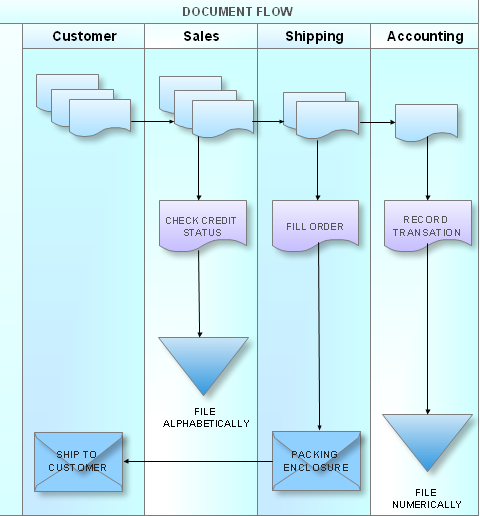
Take all the advantage of your drawing software to learn and create such a well-designed flowcharts.
Watch the HowTo video to learn more.
Electrical Symbols — Power Sources

26 libraries of the Electrical Engineering Solution of ConceptDraw DIAGRAM make your electrical diagramming simple, efficient, and effective. You can simply and quickly drop the ready-to-use objects from libraries into your document to create the electrical diagram.
Telecommunication networks. Computer and Network Examples

This example was created in ConceptDraw DIAGRAM using the Computer and Networks Area of ConceptDraw Solution Park and shows the Telecommunications network.

The vector stencils library "Transmission paths" contains 43 symbols of power transmission paths, electronic circuits, bus connectors and elbows, terminals, junctions, and concentrators.
Use it to annotate electrical diagrams, electronic schematics and circuit diagrams.
"A physical medium in data communications is the transmission path over which a signal propagates.
Many transmission media are used as communications channel.
For telecommunications purposes in the United States, Federal Standard 1037C, transmission media are classified as one of the following:
(1) Guided (or bounded) - waves are guided along a solid medium such as a transmission line.
(2) Wireless (or unguided) - transmission and reception are achieved by means of an antenna.
One of the most common physical medias used in networking is copper wire. Copper wire to carry signals to long distances using relatively low amounts of power. The unshielded twisted pair (UTP) is eight strands of copper wire, organized into four pairs.
Another example of a physical medium is optical fiber, which has emerged as the most commonly used transmission medium for long-distance communications. Optical fiber is a thin strand of glass that guides light along its length.
Multimode and single mode are two types of commonly used optical fiber. Multimode fiber uses LEDs as the light source and can carry signals over shorter distances, about 2 kilometers. Single mode can carry signals over distances of tens of miles.
Wireless media may carry surface waves or skywaves, either longitudinally or transversely, and are so classified.
In both communications, communication is in the form of electromagnetic waves. With guided transmission media, the waves are guided along a physical path; examples of guided media include phone lines, twisted pair cables, coaxial cables, and optical fibers. Unguided transmission media are methods that allow the transmission of data without the use of physical means to define the path it takes. Examples of this include microwave, radio or infrared. Unguided media provide a means for transmitting electromagnetic waves but do not guide them; examples are propagation through air, vacuum and seawater.
The term direct link is used to refer to the transmission path between two devices in which signals propagate directly from transmitters to receivers with no intermediate devices, other than amplifiers or repeaters used to increase signal strength. This term can apply to both guided and unguided media.
A transmission may be simplex, half-duplex, or full-duplex.
In simplex transmission, signals are transmitted in only one direction; one station is a transmitter and the other is the receiver. In the half-duplex operation, both stations may transmit, but only one at a time. In full duplex operation, both stations may transmit simultaneously. In the latter case, the medium is carrying signals in both directions at same time." [Transmission medium. Wikipedia]
The shapes example "Design elements - Transmission paths" was drawn using the ConceptDraw PRO diagramming and vector drawing software extended with the Electrical Engineering solution from the Engineering area of ConceptDraw Solution Park.
Transmission path symbols

Total Quality Management Definition

- The Generation Transmission And Reception Of Radio Waves
- Radio Wave Symbol
- Generation Transmission And Reception Of Radio Waves
- Radio Wave Visio Symbol
- Radio Waves Symbol For Visio
- Electromagnetic Wave Symbol
- Microwave Wave Symbol
- Design elements - VHF UHF SHF | Hf Uhf Symbol
- Symbol For Vhf Radio
- Electrical Symbols — Stations | Electrical Symbols , Electrical ...
- Radio Wave Circuits
- Radio Transmission Symbol Png
- Electrical Symbols — VHF UHF SHF | Electrical Symbols ...
- Design elements - VHF UHF SHF | Electrical Symbols — Delay ...
- Drawing Of Radio Wave Transmission
- Design elements - Stations | Electrical Symbols — Transmission ...
- Electrical Symbols — Transmission Paths | Design elements - VHF ...
- Radar Symbol
- 1918 Spanish Flu waves | Electrical Symbols — Transmission Paths ...
- Electrical Symbols — Stations | Design elements - Stations | Network ...
- ERD | Entity Relationship Diagrams, ERD Software for Mac and Win
- Flowchart | Basic Flowchart Symbols and Meaning
- Flowchart | Flowchart Design - Symbols, Shapes, Stencils and Icons
- Flowchart | Flow Chart Symbols
- Electrical | Electrical Drawing - Wiring and Circuits Schematics
- Flowchart | Common Flowchart Symbols
- Flowchart | Common Flowchart Symbols