Activity on Node Network Diagramming Tool

This sample shows the Activity on node network diagramming method. It was created in ConceptDraw DIAGRAM diagramming and vector drawing software using the Seven Management and Planning Tools solution from the Management area of ConceptDraw Solution Park.
UML Class Diagram Generalization Example UML Diagrams

This sample describes the use of the classes, the generalization associations between them, the multiplicity of associations and constraints. Provided UML diagram is one of the examples set that are part of Rapid UML solution.
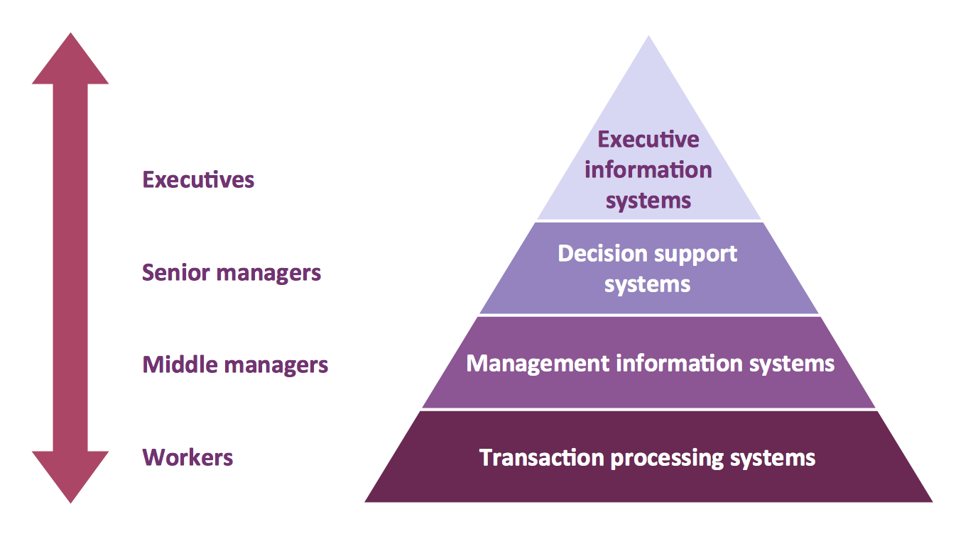
Pyramid Diagram
Booch OOD Diagram

UML Collaboration Diagram Example Illustration

This sample shows the creation process of the contact list and can be used at the staff training and staff working, at the attraction process the new clients.
UML Class Diagram Constructor

The Rapid UML Solution for ConceptDraw DIAGRAM includes the UML Class Diagram library that helps you to design the UML Class Diagram quick and easy. You can simply and quickly drop the ready-to-use objects from the library into your document to create the UML Class Diagram.
UML Class Diagram Notation

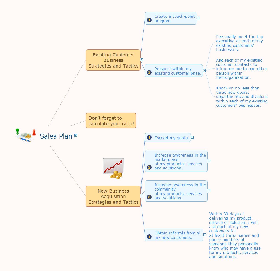
Sales Plan
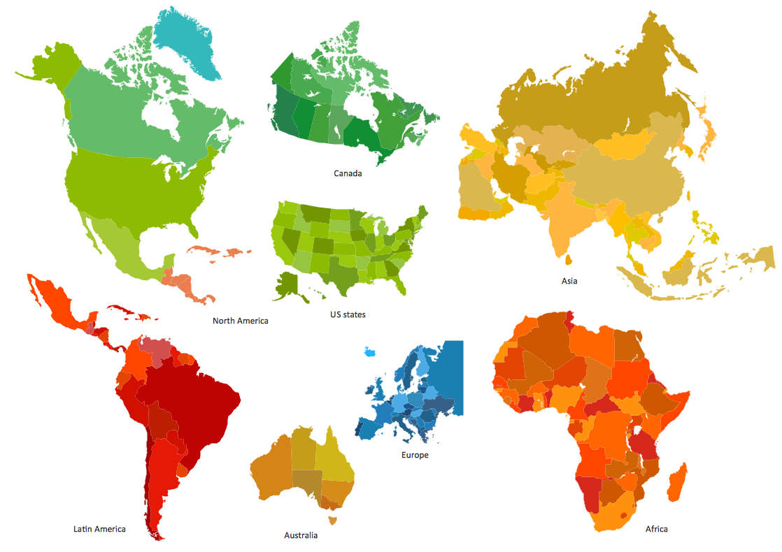
Best Tool for Infographic Construction
UML Class Diagram. Design Elements

UML Object Diagram. Design Elements

ConceptDraw has 393 vector stencils in the 13 libraries that helps you to start using software for designing your own UML Diagrams. You can use the appropriate stencils of UML notation from UML Object library.
UML Collaboration Diagram. Design Elements

ConceptDraw has 393 vector stencils in the 13 libraries that helps you to start using software for designing your own UML Diagrams. You can use the appropriate stencils of UML notation from UML Collaboration library with 36 objects
Think and act effectively
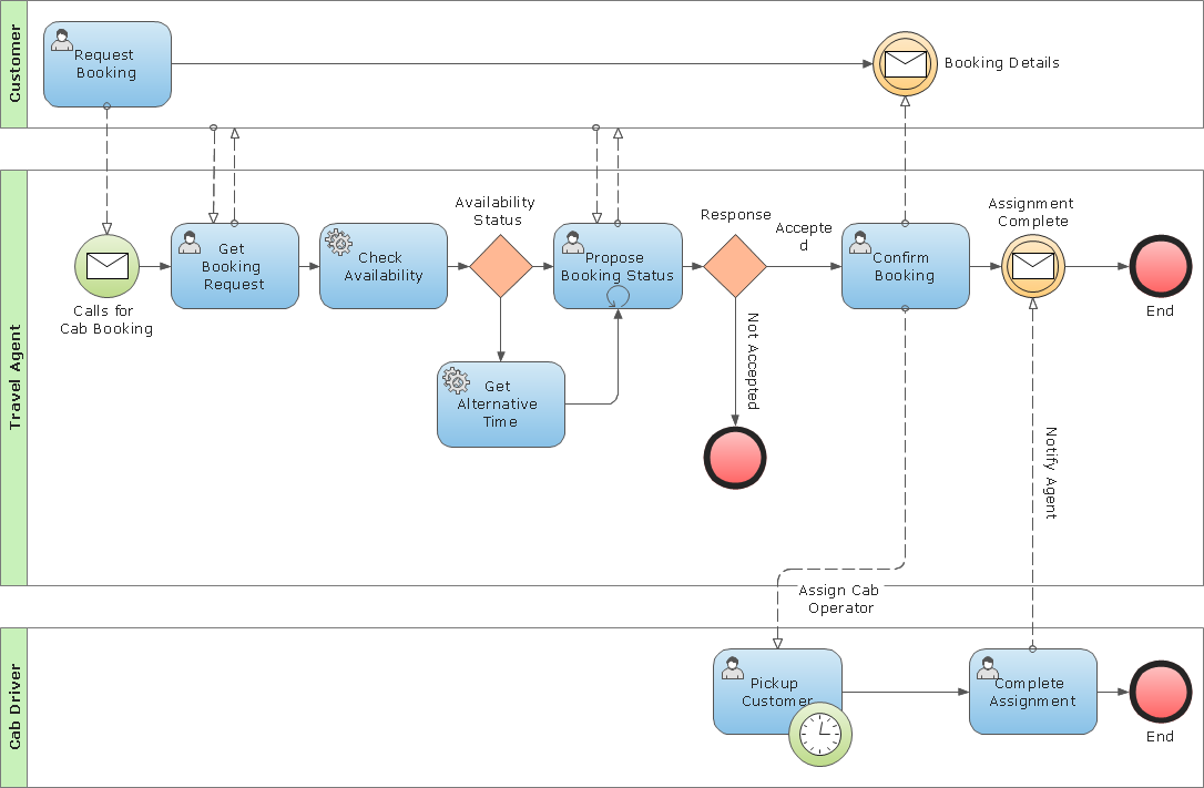
Business Process Modeling Notation Template
UML Composite Structure Diagram. Design Elements

ConceptDraw has 393 vector stencils in the 13 libraries that helps you to start using software for designing your own UML Diagrams. You can use the appropriate stencils of UML notation from UML Composite Structure library.
- Project Management Association
- How to Design a Garden Using ConceptDraw PRO | Sales ...
- Association football (soccer) formation 2–3–5 (pyramid) | Basketball ...
- Project Management Area | Software development with ...
- Gant Chart in Project Management | Booch OOD Diagram | Program ...
- Gant Chart in Project Management | Gantt chart examples | Booch ...
- Basketball Court Dimensions | Ice Hockey Rink Dimensions | Project ...
- Software Project Management Uml Diagrams
- Booch OOD Diagram | Gant Chart in Project Management | Chore ...
- Gant Chart in Project Management | How to Discover Critical Path ...
- Project Management Area | Primary Level Football Field Dimension
- Project management - Design Elements | Business and Finance ...
- Process Flowchart | Project management - Design Elements ...
- How To Use Collaboration Tool in Project Management | Tool for ...
- Process Flowchart | Quality Project Management with Mind Maps ...
- Gant Chart in Project Management | Gantt chart examples | How To ...
- UML Package Diagram. Design Elements | Design Elements for ...
- Soccer (Football) Positions | Ice Hockey Diagram – Penalty Kill ...
- Entity Relationship Diagram Software Engineering | Gant Chart in ...
- Gant Chart in Project Management | Gantt chart examples | Process ...
- ERD | Entity Relationship Diagrams, ERD Software for Mac and Win
- Flowchart | Basic Flowchart Symbols and Meaning
- Flowchart | Flowchart Design - Symbols, Shapes, Stencils and Icons
- Flowchart | Flow Chart Symbols
- Electrical | Electrical Drawing - Wiring and Circuits Schematics
- Flowchart | Common Flowchart Symbols
- Flowchart | Common Flowchart Symbols