This purchase order processing UML activity diagram was created on the base of activity diagram from the software architecture documentation wiki of the Software Engineering Institute (SEI) of Carnegie Mellon University (CMU).
[wiki.sei.cmu.edu/ sad/ index.php/ Image:PurchaseOrderActivityDiagram.png]
"A purchase order (PO) is a commercial document and first official offer issued by a buyer to a seller, indicating types, quantities, and agreed prices for products or services. Acceptance of a purchase order by a seller forms a contract between the buyer and seller, so no contract exists until the purchase order is accepted. It is used to control the purchasing of products and services from external suppliers.
Creating a purchase order is typically the first step of the purchase to pay process in an ERP system." [Purchase order. Wikipedia]
This purchase order processing UML activity diagram example was created using the ConceptDraw PRO diagramming and vector drawing software extended with the ATM UML Diagrams solution from the Software Development area of ConceptDraw Solution Park.
UML activity diagram of purchase order processing

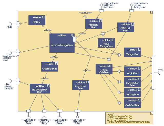
This UML sequence diagram of order processing center (OPC) was created on the base of sequence diagram from the software architecture documentation wiki of the Software Engineering Institute (SEI) of Carnegie Mellon University (CMU).
[wiki.sei.cmu.edu/ sad/ index.php/ Image:OPCRuntimeRefinementView_ PP2.png]
"Order processing is the process or work-flow associated with the picking, packing and delivery of the packed items to a shipping carrier. Order processing is a key element of order fulfillment. Order processing operations or facilities are commonly called "distribution centers"." [Order processing. Wikipedia]
This order processing center UML sequence diagram example was created using the ConceptDraw PRO diagramming and vector drawing software extended with the ATM UML Diagrams solution from the Software Development area of ConceptDraw Solution Park.
Order processing center UML sequence diagram
How to Create a Cross Functional Flow Chart

ConceptDraw Arrows10 Technology - This is more than enough versatility to draw any type of diagram with any degree of complexity.
Drawing software lets you to make horizontal and vertical, audit, opportunity and many more flowcharts.
- Processing Documentation
- Visa Processing System Project Documentation
- Process Flowchart | Accounting Flowchart Symbols | Processing ...
- What Are The Diagrams For Documentation Purchase
- Shipping Documentation Process
- Process Flowchart | Credit Card Processing System UML Diagram ...
- Invoice payment process - Flowchart | Accounting Flowchart ...
- Purchase order processing UML activity diagram | UML Tool & UML ...
- Sequence Diagram Tool | Order processing center - UML sequence ...
- Purchase order processing UML activity diagram
- Cross-Functional Flowchart | Visa Processing System Activity Diagram
- Event-driven Process Chain Diagrams | Purchase order processing ...
- UML Diagram | Purchase order processing UML activity diagram ...
- Cross-Functional Flowchart | Activity Diagram For Visa Processing ...
- Purchase order processing UML activity diagram | UML Activity ...
- Processing Flow Chart | Invoice payment process - Flowchart | Flow ...
- Order processing - Cross-functional flowchart | Order processing ...
- UML use case diagram - Ticket processing system | UML Tool ...
- Process Flowchart | Block Diagram | Block diagram - Document ...
- Payment Processing System Flow Chart
- ERD | Entity Relationship Diagrams, ERD Software for Mac and Win
- Flowchart | Basic Flowchart Symbols and Meaning
- Flowchart | Flowchart Design - Symbols, Shapes, Stencils and Icons
- Flowchart | Flow Chart Symbols
- Electrical | Electrical Drawing - Wiring and Circuits Schematics
- Flowchart | Common Flowchart Symbols
- Flowchart | Common Flowchart Symbols