The vector stencils library "Chemical engineering" contains 24 symbols of chemical and process engineering equipment.
Use these shapes for drawing Process Flow Diagrams (PFD), Piping and Instrumentation Diagrams (P&ID), and Water Flow Diagrams in the ConceptDraw PRO software extended with the Chemical and Process Engineering solution from the Chemical and Process Engineering area of ConceptDraw Solution Park.
www.conceptdraw.com/ solution-park/ engineering-chemical-process
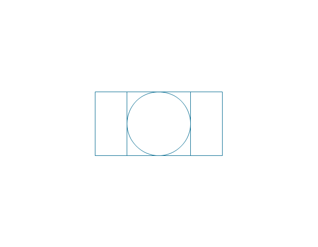
Clarifier

Screen

Filter

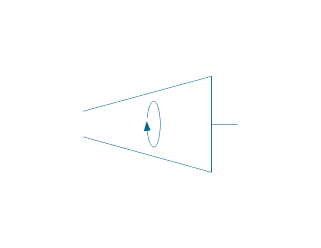
Agitator

Vapor 1

Vapor 2

Vessel

Pump mixer

Centrifugal pump

Fan

Blower

Evaporator

Tower

Flash drum

Roll press

Cooling tower

Tank car

Tank truck

Kettle

Valve

Motor valve

Venturi

Propeller

Instrument

The vector stencils library "Chemical engineering" contains 24 symbols of chemical and process engineering equipment.
Use these shapes for drawing block flow diagrams (BFD), process flow diagrams (PFD), piping and instrumentation diagrams (P&ID), and water flow diagrams.
"Chemical engineering is a branch of engineering that applies the natural (or experimental) sciences (e.g., chemistry and physics) and life sciences (e.g. biology, microbiology and biochemistry) together with mathematics and economics to production, transformation, transportation and proper usage of chemicals, materials and energy. It essentially deals with the engineering of chemicals, energy and the processes that create and/ or convert them. Modern chemical engineers are concerned with processes that convert raw-materials or (cheap)chemicals into more useful or valuable forms. In addition, they are also concerned with pioneering valuable materials and related techniques – which are often essential to related fields such as nanotechnology, fuel cells and bioengineering. Within chemical engineering, two broad subgroups include design, manufacture, and operation of plants and machinery in industrial chemical and related processes ("chemical process engineers") and development of new or adapted substances for products ranging from foods and beverages to cosmetics to cleaners to pharmaceutical ingredients, among many other products ("chemical product engineers")." [Chemical engineering. Wikipedia]
The example "Design elements - Chemical engineering" was created using the ConceptDraw PRO diagramming and vector drawing software extended with the Chemical and Process Engineering solution from the Engineering area of ConceptDraw Solution Park.
Chemical engineering symbols

This vector stencils library contains 22 symbols of process annotations for setting automatic labels to display a datasheet field for a pipeline shape, labels, captions, outlines, off-sheet labels, text balloons, annotations, outlines, tags, and descriptions.
Use these shapes for drawing Process Flow Diagrams (PFD) and Piping and Instrumentation Diagrams (P&ID) in the ConceptDraw PRO software extended with the Chemical and Process Engineering solution from the Chemical and Process Engineering area of ConceptDraw Solution Park.
www.conceptdraw.com/ solution-park/ engineering-chemical-process
Interface point

Interface point 2 (1st half filled)
-process-annotations---vector-stencils-library.png--diagram-flowchart-example.png)
Interface point 3 (2nd half filled)
-process-annotations---vector-stencils-library.png--diagram-flowchart-example.png)
Interface point 4

Interface point 5 (1st half filled)
-process-annotations---vector-stencils-library.png--diagram-flowchart-example.png)
Interface point 6 (2nd half filled)
-process-annotations---vector-stencils-library.png--diagram-flowchart-example.png)
Slope

Off-sheet label 1

Off-sheet label 2

Off-sheet label 3

Callout 1

Callout 2

Callout 3

Callout 4

Callout 5

Callout 6

8 pt text and line

10 pt text and line

12 pt text and line

12 pt Arial text block

10 pt Arial text block

8 pt Arial text block

The vector stencils library "Process annotations" contains 22 symbols of interface points, slope, off-sheet labels, callouts and textboxes.
Use these shapes for setting automatic labels to display a datasheet field for a pipeline shape, labels, captions, outlines, off-sheet labels, text balloons, annotations, outlines, tags, and descriptions.
"In engineering a process is a set of interrelated tasks that, together, transform inputs into outputs. These tasks may be carried out by people, nature, or machines using resources; so an engineering process must be considered in the context of the agents carrying out the tasks, and the resource attributes involved. Systems Engineering normative documents and those related to Maturity Models are typically based on processes. For example, System Engineering processes of the EIA-632 and processes involved in the Capability Maturity Model Integration (CMMI) institutionalization and improvement approach. Constraints imposed on the tasks and resources required to implement them are essential for executing the tasks mentioned.
A chemical process is a series of unit operations used to produce a material in large quantities.
In the chemical industry, chemical engineers will use the following to define or illustrate a process:
Process Flow Diagram (PFD),
Piping and instrumentation diagram
(P&ID),
Simplified process description,
Detailed process description,
Project management,
Process simulation." [Process (engineering). Wikipedia]
The example "Design elements - Process annotations" was created using the ConceptDraw PRO diagramming and vector drawing software extended with the Chemical and Process Engineering solution from the Engineering area of ConceptDraw Solution Park.
Process annotation symbols

Process Flow Diagram Symbols

 Event-driven Process Chain Diagrams
Event-Driven Process Chain Diagrams solution extends ConceptDraw DIAGRAM functionality with event driven process chain templates, samples of EPC engineering and modeling the business processes, and a vector shape library for drawing the EPC diagrams and EPC flowcharts of any complexity. It is one of EPC IT solutions that assist the marketing experts, business specialists, engineers, educators and researchers in resources planning and improving the business processes using the EPC flowchart or EPC diagram. Use the EPC solutions tools to construct the chain of events and functions, to illustrate the structure of a business process control flow, to describe people and tasks for execution the business processes, to identify the inefficient businesses processes and measures required to make them efficient.
The vector stencils library "Industrial equipment" contains 81 symbols of pumps, compressors, fans, turbines, and power generators.
Use these shapes to design pumping systems, air and fluid compression systems, and industrial process diagrams.
"Process engineering focuses on the design, operation, control, and optimization of chemical, physical, and biological processes. Process engineering encompasses a vast range of industries, such as chemical, petrochemical, mineral processing, advanced material, food, pharmaceutical, and biotechnological industries. The application of systematic computer-based methods to process engineering is process systems engineering." [Process engineering. Wikipedia]
The example "Design elements - Industrial equipment" was created using the ConceptDraw PRO diagramming and vector drawing software extended with the Chemical and Process Engineering solution from the Engineering area of ConceptDraw Solution Park.
Industrial equipment symbols

Graphical Symbols to use in EPC diagrams

ConceptDraw DIAGRAM - software that reduces the time needed to create a business process model.
Cisco Security. Cisco icons, shapes, stencils and symbols

Flowchart design. Flowchart symbols, shapes, stencils and icons

Mavericks have always desired to stand apart and gorgeous design is the recipe for that. Any business graphic document will be more understandable if will use an expository color scheme for their parts. Flowchart design makes versatile presenting and explaining of the process and gives a fresh view that distinguishes it from black and white flowcharts on a paper. Workflow diagram or process flow diagrams become more understandable to ordinary people when it use minimum symbols and special signs.
The best design can be accomplished by starting from any of the suitable Conceptdraw examples. Pick one of them and begin to input proper text into each Flowchart symbols and shapes. Apply less colors in the document and don't turn into rainbow your diagram, three or four will be enough, also note that business process flowchart may not contain bright color hues. The next clue is to use identical colors for same flowchart shape types.

The vector stencils library "Industrial equipment" contains 81 symbols of pumps, compressors, fans, turbines, and power generators.
Use these shapes to design pumping systems, air and fluid compression systems, and industrial process diagrams in the ConceptDraw PRO software extended with the Chemical and Process Engineering solution from the Chemical and Process Engineering area of ConceptDraw Solution Park.
www.conceptdraw.com/ solution-park/ engineering-chemical-process
Breaker

Crusher

Crusher coarse

Crusher medium

Crusher fine

Roll crusher

Hammer crusher

Crusher single load

Crusher hammer

Crusher impact

Crusher jaw

Crusher high-speed roller

Crusher cone

Crusher cone 2
Crusher general

Crusher hammer 2

Crusher impact 2
Crusher jaw 2
Crusher roller
Ball mill

Mill general

Mill hammer

Mill impact

Mill jet

Mill roller

Mill vibrator

Mixer

Mixer general

Mixer rotary

Mixer can

Mixer fluidized

Kneader

Kneader general

Kneader wheel

Kneader ball

Kneader rolling

Kneader blade

Blender

Double blender

Fluid separator general

Fluid separator wet

Fluid separator dry

Fluid separator gravitation

Fluid separator inertial

Fluid separator centrifugal

Filter 1
Filter 2

Rotary filter

Screen

Electromagnet

Cyclone 1

Cyclone 2

Centrifuge general

Centrifuge dehydrator

Centrifuge submersion
Centrifuge 2

Briquetting machine standard

Briquetting machine

Prill tower

Dryer

Conveyor 2 circles 2 lines

Conveyor 2 circles 1 line

Conveyor 1 circle 2 lines

Conveyor 1 circle 1 line

Conveyor wheel

Boom loader

Scraper conveyor

Screw conveyor

Screw conveyor 2

Elevator 1

Elevator 2

Skip hoist

Overhead conveyor

Overhead conveyor with hooks

Overhead conveyor with buckets

Hoist

Hoist with hook

Hoist with grab

Electric motor

Tank truck

Tank car

The vector stencils library "Instruments" contains 72 symbols of control instruments and measuring devices: meters and gauges, and callouts, text boxes, and inserts.
Use these shapes to create annotated process flow diagrams (PFD), flow control, manufacturing processes, and distribution system diagrams in the ConceptDraw PRO software extended with the Chemical and Process Engineering solution from the Chemical and Process Engineering area of ConceptDraw Solution Park.
www.conceptdraw.com/ solution-park/ engineering-chemical-process
Indicator local

Indicator remote

Indicator auxiliary

CRT local

CRT remote

CRT auxiliary

PLC local

PLC auxiliary

PLC remote

Computer local

Computer auxiliary

Computer remote

Light local

Light remote

Light auxiliary

Indicator auxiliary (dashed)
-instruments---vector-stencils-library.png--diagram-flowchart-example.png)
Indicator remote (dashed)
-instruments---vector-stencils-library.png--diagram-flowchart-example.png)
Steam traced auxiliary

Steam traced remote

Steam traced local

Level meter auxiliary

Level meter remote

Level meter local

Pressure gauge diaphragm

Pressure gauge

Pressure gauge liquid filled

Strain gauge

Thermometer bi-metallic

Thermometer gas

Thermometer general

Thermometer glass

Thermometer liquid

Thermometer resistance

Thermometer thermocouple

Flowmeter electromagnetic

Flowmeter general

Flowmeter nozzle

Flowmeter orifice

Flowmeter positive displacement

Flowmeter turbine

Flowmeter variable area

Flowmeter Venturi

Level meter capacitive

Level meter conductive

Level meter displacer

Level meter float

Level meter general

Level meter sonic

Indicator analoque

Indicator digital

Indicator general

Recorder analoque

Recorder digital

Recorder general

Converter

Converter 2 (1st half filled)
-instruments---vector-stencils-library.png--diagram-flowchart-example.png)
Converter 3 (2nd half filled)
-instruments---vector-stencils-library.png--diagram-flowchart-example.png)
Venturi

Venturi (pressure taps)
-instruments---vector-stencils-library.png--diagram-flowchart-example.png)
Flowmeter

Rotameter

Vortex sensor

Propeller meter

Generic utility

Operator box

Operator box 2 (1st half filled)
-instruments---vector-stencils-library.png--diagram-flowchart-example.png)
Operator box 3 (2nd half filled)
-instruments---vector-stencils-library.png--diagram-flowchart-example.png)
AND gate

OR gate

NOT gate

Correcting element

Diamond

Process Flowchart


Cross-Functional Process Map Template

Use templates with process maps, diagrams, charts to get the drawing in minutes.
ConceptDraw Arrows10 Technology

AWS icons 2.0

Used for:create Web Application Architecture, architect infrastructure based on AWS® (Amazon Web Services), design application services based on AWS® (Amazon Web Services), design auto-scalable architecture, design for elastic compute cloud, illustrate whitepapers and presentations, create vector graphics files.
The vector stencils library "Heating equipment" contains 42 symbols of regenerators, intercoolers, heaters, and condensers.
Use these shapes for drawing cooling systems, heat recovery systems, thermal, heat transfer and mechanical design, and process flow diagrams (PFD) in the ConceptDraw PRO software extended with the Chemical and Process Engineering solution from the Chemical and Process Engineering area of ConceptDraw Solution Park.
www.conceptdraw.com/ solution-park/ engineering-chemical-process
Heat exchanger 3

Heat exchanger 1

Heat exchanger 2

Tube bundle, floating head

U-Tube bundle

Tube bundle

Shell and tube

Kettle reboiler

Plate type

Finned tube

Double pipe type

Oil burner

Boiler

Fired heater

Cooling tower 2

Cooling tower 1

Cooling tower 3

Condenser

Automatic stoker

Refrigerator

Direct refrigerator

Indirect refrigerator

Evaporative condenser

Condenser (air cooled)
-heating-equipment---vector-stencils-library.png--diagram-flowchart-example.png)
Oil separator

Chilling evaporator

Air cooling evaporator

Extractor hood (slot)
-heating-equipment---vector-stencils-library.png--diagram-flowchart-example.png)
Extractor hood (open)
-heating-equipment---vector-stencils-library.png--diagram-flowchart-example.png)
Autoclave (propeller)
-heating-equipment---vector-stencils-library.png--diagram-flowchart-example.png)
Autoclave (anchor)
-heating-equipment---vector-stencils-library.png--diagram-flowchart-example.png)
Autoclave (helical)
-heating-equipment---vector-stencils-library.png--diagram-flowchart-example.png)
Autoclave with motor (helical)
-heating-equipment---vector-stencils-library.png--diagram-flowchart-example.png)
Autoclave with motor (anchor)
-heating-equipment---vector-stencils-library.png--diagram-flowchart-example.png)
Autoclave with motor (propeller)
-heating-equipment---vector-stencils-library.png--diagram-flowchart-example.png)
Fan blades horizontal

Fan blades vertical

Fan blades (4)
-heating-equipment---vector-stencils-library.png--diagram-flowchart-example.png)
Triple fan blades

Air-blown cooler

Condenser

Heater / Cooler

Cisco Network Design. Cisco icons, shapes, stencils, symbols and design elements

Process Flow Chart Symbols

It is incredibly convenient to use the ConceptDraw DIAGRAM software extended with Flowcharts Solution from the "Diagrams" Area of ConceptDraw Solution Park for designing professional looking Process Flow Charts.
Standard Shapes for Value Stream Mapping

- Visio Process Engineering Shapes
- Chemical engineering - Vector stencils library | Design elements ...
- Process Engineering
- Visio Chemical Engineering Shapes
- Chemical engineering - Vector stencils library | How Do I Draw A ...
- Visio Chemical Engineering Shapes Download
- Flowchart Software | Chemical and Process Engineering | Electrical ...
- Chemical and Process Engineering | In searching of alternative to ...
- Chemical and Process Engineering | Process Engineering | IDEF0 ...
- Process Flow Diagram Symbols | Design elements - Heating ...
- Chemical and Process Engineering | Mechanical Engineering ...
- Process Flow Diagram Symbols | Chemical Engineering | Chemical ...
- Visio Process Equipment Shapes
- Chemical and Process Engineering | How to Draw a Chemical ...
- Chemical engineering - Vector stencils library | Chemical ...
- Watercraft - Design Elements | Process Flow Diagram Symbols ...
- Process Flow Diagram Symbols | Chemical Engineering | Process ...
- Chemical and Process Engineering | Interior Design. Piping Plan ...
- Visio Engineering Shapes Free
- How to Draw Chemistry Structures | Chemical and Process ...
- ERD | Entity Relationship Diagrams, ERD Software for Mac and Win
- Flowchart | Basic Flowchart Symbols and Meaning
- Flowchart | Flowchart Design - Symbols, Shapes, Stencils and Icons
- Flowchart | Flow Chart Symbols
- Electrical | Electrical Drawing - Wiring and Circuits Schematics
- Flowchart | Common Flowchart Symbols
- Flowchart | Common Flowchart Symbols