The vector stencils library "Vessels" contains 40 symbols of vessels, containers, tanks, drums, and basins.
Use these shapes for drawing process flow diagrams (PFD), materials handling systems, and feed systems in industrial and manufacturing processes.
"A pressure vessel is a closed container designed to hold gases or liquids at a pressure substantially different from the ambient pressure.
The pressure differential is dangerous and fatal accidents have occurred in the history of pressure vessel development and operation. Consequently, pressure vessel design, manufacture, and operation are regulated by engineering authorities backed by legislation. For these reasons, the definition of a pressure vessel varies from country to country, but involves parameters such as maximum safe operating pressure and temperature." [Pressure vessel. Wikipedia]
The example "Design elements - Vessels" was created using the ConceptDraw PRO diagramming and vector drawing software extended with the Chemical and Process Engineering solution from the Engineering area of ConceptDraw Solution Park.
Vessel symbols
 Chemical and Process Engineering
This chemical engineering solution extends ConceptDraw DIAGRAM.9.5 (or later) with process flow diagram symbols, samples, process diagrams templates and libraries of design elements for creating process and instrumentation diagrams, block flow diagrams (BFD
Building Drawing. Design Element: Piping Plan


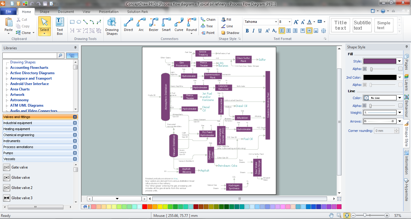
Process Flow Diagram

ConceptDraw DIAGRAM diagramming and vector drawing software extended with powerful tools of Flowcharts Solution from the "Diagrams" Area of ConceptDraw Solution Park is effective for drawing: Process Flow Diagram, Flow Process Diagram, Business Process Flow Diagrams.
Process Flow Diagram Symbols

Chemical Engineering

Process Engineering
Technical Drawing Software

ConceptDraw DIAGRAM extended with: Mechanical Engineering Solution, Electrical Engineering Solution, Chemical and Process Engineering Solution from the Industrial Engineering Area is powerful software for business and technical drawing. Its powerful drawing tools, predesigned vector objects, templates, samples are helpful for creation all kinds of Technical Drawings and Technical Diagrams, Electrical and Mechanical Schematics, Circuit and Wiring Diagrams, Structural Drawings, and many other.
This PFD sample was redesigned from the Wikipedia file: NaturalGasCondensate.png.
"This is a schematic flow diagram of a typical facility for separating and recovering liquid condensate from raw natural gas."
[en.wikipedia.org/ wiki/ File:NaturalGasCondensate.png]
"Natural-gas condensate is a low-density mixture of hydrocarbon liquids that are present as gaseous components in the raw natural gas produced from many natural gas fields. It condenses out of the raw gas if the temperature is reduced to below the hydrocarbon dew point temperature of the raw gas.
The natural gas condensate is also referred to as simply condensate, or gas condensate, or sometimes natural gasoline because it contains hydrocarbons within the gasoline boiling range. Raw natural gas may come from any one of three types of gas wells:
(1) Crude oil wells - Raw natural gas that comes from crude oil wells is called associated gas. This gas can exist separate from the crude oil in the underground formation, or dissolved in the crude oil.
(2) Dry gas wells - These wells typically produce only raw natural gas that does not contain any hydrocarbon liquids. Such gas is called non-associated gas.
(3) Condensate wells - These wells produce raw natural gas along with natural gas liquid. Such gas is also non-associated gas and often referred to as wet gas." [Natural-gas condensate. Wikipedia]
The process flow diagram example "Natural gas condensate - PFD" was drawn using the ConceptDraw PRO software extended with the Chemical and Process Engineering solution from the Chemical and Process Engineering area of ConceptDraw Solution Park.
Process flow diagram (PFD)
-natural-gas-condensate---pfd.png--diagram-flowchart-example.png)
- Symbols On Pressure Vessel
- Pressure Vessels Process Flow Chart
- Design elements - Vessels | Vessels - Vector stencils library ...
- Open Storage Tank Design
- Pressure Vessel Plans
- Design elements - Vessels | Design elements - Storage and ...
- Design elements - Vessels | Design elements - Fault tree analysis ...
- Design elements - Shipping and receiving | Design elements ...
- Design elements - Vessels | Symbol Of Ambient Temperature
- Piping and Instrumentation Diagram Software | Vessels - Vector ...
- Process Flow Diagram Symbols | Design elements - Vessels ...
- Design elements - Vessels | Process Flow Diagram | Design ...
- Design elements - Vessels | Vessels - Vector stencils library | Interior ...
- Process Flow Diagram | Pressure Vessel Flow Process Chart
- Piping and Instrumentation Diagram Software | Vessels - Vector ...
- Vessels - Vector stencils library | Design elements - Vessels ...
- Vessels - Vector stencils library | Crude oil distillation unit - PFD ...
- Pressure Vessel Diagram In Oil Refinery
- Design elements - Walls, shell and structure | Vessels - Vector ...
- Chemical Vessel
- ERD | Entity Relationship Diagrams, ERD Software for Mac and Win
- Flowchart | Basic Flowchart Symbols and Meaning
- Flowchart | Flowchart Design - Symbols, Shapes, Stencils and Icons
- Flowchart | Flow Chart Symbols
- Electrical | Electrical Drawing - Wiring and Circuits Schematics
- Flowchart | Common Flowchart Symbols
- Flowchart | Common Flowchart Symbols