Physical network. Computer and Network Examples

This example was created in ConceptDraw DIAGRAM using the Computer and Networks Area of ConceptDraw Solution Park and shows the Physical star network.

Network Diagram Software Physical Network Diagram

Diagram Physical Topologies

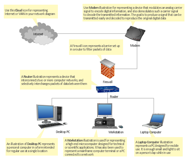
This diagram shows the physical network topology. Network topology is the topological structure of the computer network. The physical network topology depicts the placement of the components in the network. It shows the configuration of cables, computers, and other devices.
Network Diagram Software. LAN Network Diagrams. Physical Office Network Diagrams

Physical Activity Plan

Local area network (LAN). Computer and Network Examples
 diagram")
ConceptDraw - Perfect Network Diagramming Software with examples of LAN Diagrams. ConceptDraw Network Diagram is ideal for network engineers and network designers who need to draw Local Area Network diagrams.
Physical Security Plan

"At different scales diagrams may represent various levels of network granularity. At the LAN level, individual nodes may represent individual physical devices, such as hubs or file servers, while at the WAN level, individual nodes may represent entire cities. In addition, when the scope of a diagram crosses the common LAN/ MAN/ WAN boundaries, representative hypothetical devices may be depicted instead of showing all actually existing nodes. For example, if a network appliance is intended to be connected through the Internet to many end-user mobile devices, only a single such device may be depicted for the purposes of showing the general relationship between the appliance and any such device." [Computer network diagram. Wikipedia]
The physical LAN and WAN diagram template for the ConceptDraw PRO diagramming and vector drawing software is included in the Computer and Networks solution from the Computer and Networks area of ConceptDraw Solution Park.
The physical LAN and WAN diagram template for the ConceptDraw PRO diagramming and vector drawing software is included in the Computer and Networks solution from the Computer and Networks area of ConceptDraw Solution Park.
Physical LAN and WAN diagram template
"Physical topology refers to the placement of the network's various components, including device location and cable installation...
The shape of the cabling layout used to link devices is called the physical topology of the network. This refers to the layout of cabling, the locations of nodes, and the interconnections between the nodes and the cabling. The physical topology of a network is determined by the capabilities of the network access devices and media, the level of control or fault tolerance desired, and the cost associated with cabling or telecommunications circuits." [Network topology. Wikipedia]
This physical LAN diagram example was created using the ConceptDraw PRO diagramming and vector drawing software extended with the Computer and Networks solution from the Computer and Networks area of ConceptDraw Solution Park.
LAN physical topology

Used Solutions
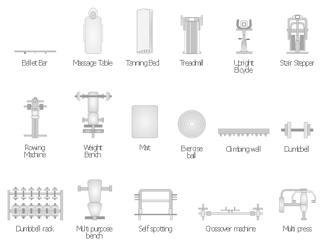
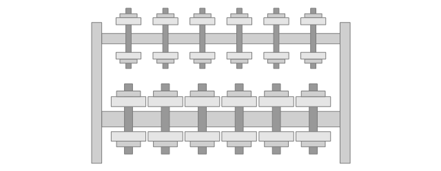
The vector stencils library "Physical training" contains 9 symbols of exercise equipment.
"Exercise equipment is any apparatus or device used during physical activity to enhance the strength or conditioning effects of that exercise by providing either fixed or adjustable amounts of resistance, or to otherwise enhance the experience or outcome of an exercise routine.
Exercise equipment may also include such items as proper footgear, gloves, hydration equipment, etc.
It is important to use exercise equipment properly: inappropriate use of equipment can lead to injuries from mild to extreme." [Exercise equipment. Wikipedia]
The example "Design elements - Physical training" was created using the ConceptDraw PRO diagramming and vector drawing software extended with the Gym and Spa Area Plans solution from the Building Plans area of ConceptDraw Solution Park.
Physical training symbols
"Physical topology refers to the placement of the network's various components, including device location and cable installation...
The shape of the cabling layout used to link devices is called the physical topology of the network. This refers to the layout of cabling, the locations of nodes, and the interconnections between the nodes and the cabling. The physical topology of a network is determined by the capabilities of the network access devices and media, the level of control or fault tolerance desired, and the cost associated with cabling or telecommunications circuits." [Network topology. Wikipedia]
The LAN cabling layout floorplan example "Local network physical topology floor plan" was created using the ConceptDraw PRO diagramming and vector drawing software extended with the Network Layout Floor Plans solution from the Computer and Networks area of ConceptDraw Solution Park.
LAN cabling layout floorplan

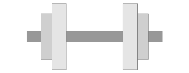
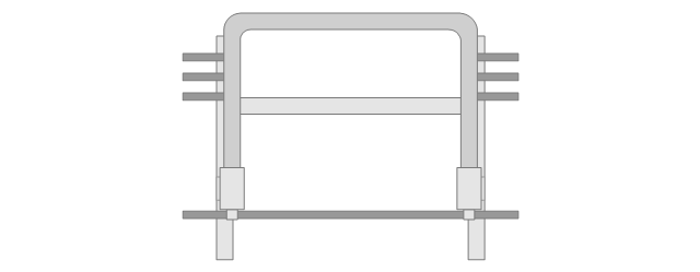
This vector stencils library contains 17 symbols of sport equipment for drawing physical training design floor plans and equipment layouts.
Ballet Bar

Climbing wall
Crossover machine
Dumbbell rack
Dumbbell
Exercise ball

Massage Table

Mat

Multi press

Multi purpose bench

Rowing Machine

Self spotting
Stair stepper

Tanning Bed

Treadmill

Upright bicycle

Weight Bench

Virtual networks. Computer and Network Examples

Well known forms of network virtualization are virtual networks based on the virtual devices (for example the network based on the virtual devices inside a hypervisor), protocol-based virtual networks (VLAN, VPN, VPLS, Virtual Wireless network, etc.) and their combinations.
This example was created in ConceptDraw DIAGRAM using the Computer and Networks Area of ConceptDraw Solution Park and shows the Virtual network.
"Logical topology, or signal topology, is the arrangement of devices on a computer network and how they communicate with one another. How devices are connected to the network through the actual cables that transmit data, or the physical structure of the network, is called the physical topology. Physical topology defines how the systems are physically connected. It represents the physical layout of the devices on the network. The logical topology defines how the systems communicate across the physical topologies.
Logical topologies are bound to network protocols and describe how data is moved across the network. ...
EXAMPLE : twisted pair Ethernet is a logical bus topology in a physical star topology layout. while IBM's token ring is a logical ring topology, it is physically set up in star topology." [Logical topology. Wikipedia]
This Cisco logical computer network diagram example was created using the ConceptDraw PRO diagramming and vector drawing software extended with the Cisco Network Diagrams solution from the Computer and Networks area of ConceptDraw Solution Park.
Logical network topology diagram

Wireless Network Topology

Wireless network topology shows how the computers connect each other when there is no physical connection. The computers communicate each using the wireless devices.
Network Topologies


Cisco Network Topology. Cisco icons, shapes, stencils and symbols

Any Cisco equipment on the network are named like node. Network diagram topology commonly designed within connected nodes. Cisco icons are worldwide acknowledged and mainly established as standard icons for network diagrams. You may use them loosely, but you may not rework them.
The Cisco Network Diagram shows how signals act on the networked devices, or how data routes on the network from one device to the other. There are number of physical network typologies that engineers use while constructing computer networks.
Professional & Powerful Mind Mapping Software

The vector stencils library "Logical symbols" contains 49 logical symbols for drawing logical network topology diagrams.
"Logical topology, or signal topology, is the arrangement of devices on a computer network and how they communicate with one another. How devices are connected to the network through the actual cables that transmit data, or the physical structure of the network, is called the physical topology. Physical topology defines how the systems are physically connected. It represents the physical layout of the devices on the network. The logical topology defines how the systems communicate across the physical topologies.
Logical topologies are bound to network protocols and describe how data is moved across the network. ... EXAMPLE : twisted pair Ethernet is a logical bus topology in a physical star topology layout. While IBM's token ring is a logical ring topology, it is physically set up in star topology." [Logical topology. Wikipedia]
The icons example "Logical symbols - Vector stencils library" was created using the ConceptDraw PRO diagramming and vector drawing software extended with the Computer and Networks solution from the Computer and Networks area of ConceptDraw Solution Park.
www.conceptdraw.com/ solution-park/ computer-and-networks
Coaxial Line Tag

Fiber Optic Line Tag

Twisted Pair Line Tag

SC2200 Signaling Controller

Bridge

Network Management Appliance

Access Server (Communications Server)
-logical-symbols---vector-stencils-library.png--diagram-flowchart-example.png)
Terminal Server

Web Browser

Security Management, Cisco

Lock and Key

Lock

Key

Relational Database

Host

CSU/DSU

WAN

University

Government building

Home Office

Telecommuter House PC

Medium Building, Regular

Headquarters, Subdued

House, Regular

Small Business

Network Connector

Dynamic Connector

Line Connector

Line-curve Connector

Bus

FDDI Ring

Peer-to-peer

Token-ring

Star

Comm-link

Curved Bus

Ethernet

Cloud

Speaker

Microphone

Router

ATM Router

ISDN Switch

ATM Switch

ATM/FastGB Etherswitch

Workgroup Switch

Small Hub

100BaseT Hub

CDDI-FDDI

Data Modeling with Entity Relationship Diagram

The best ERD tool for the Mac and Windows is ConceptDraw DIAGRAM software extended with the Entity-Relationship Diagram (ERD) solution from the Software Development Area for ConceptDraw Solution Park, which is sharpened for professional ERD drawing and data modeling with Entity Relationship Diagram.
- Diagram Physical Topologies | Physical LAN topology diagram ...
- Network Diagram Software Logical Network Diagram
- Logical network topology diagram | Physical Topology Diagrams ...
- Physical Network Diagram Vs Logical
- Difference Between Logical And Physical Data Flow Diagram
- Network diagrams with ConceptDraw DIAGRAM | Network Diagram ...
- Physical Topology Examples Diagram
- Physical LAN topology diagram | Logical network topology diagram ...
- Physical LAN and WAN diagram - Template | Network Diagram ...
- Physical LAN topology diagram | Local network physical topology ...
- Local network physical topology floor plan | How to Create a ...
- Network Diagram Software Physical Network Diagram | Design ...
- Network Diagram Software. LAN Network Diagrams. Physical Office ...
- Diagram Physical Topologies
- Physical LAN and WAN diagram - Template | Network Printer ...
- Physical LAN and WAN diagram - Template | Cisco Network Objects ...
- Logical network topology diagram | Network Diagram Software ...
- Physics Diagrams | Physics | | Physical Science Drawing
- Security Plans | Security and Access Plans | Physical Security Plan ...
- Physical network. Computer and Network Examples | Network ...
- ERD | Entity Relationship Diagrams, ERD Software for Mac and Win
- Flowchart | Basic Flowchart Symbols and Meaning
- Flowchart | Flowchart Design - Symbols, Shapes, Stencils and Icons
- Flowchart | Flow Chart Symbols
- Electrical | Electrical Drawing - Wiring and Circuits Schematics
- Flowchart | Common Flowchart Symbols
- Flowchart | Common Flowchart Symbols