Program Evaluation and Review Technique (PERT) with ConceptDraw DIAGRAM

CORRECTIVE ACTIONS PLANNING. PERT Chart
ConceptDraw Office suite is a software for corrective actions planning.

UML Class Diagram Example - Buildings and Rooms

This sample shows the structure of the building and can be used by building companies, real estate agencies, at the buying / selling of the realty.
Structured Systems Analysis and Design Method. SSADM with ConceptDraw DIAGRAM

How To Create Onion Diagram
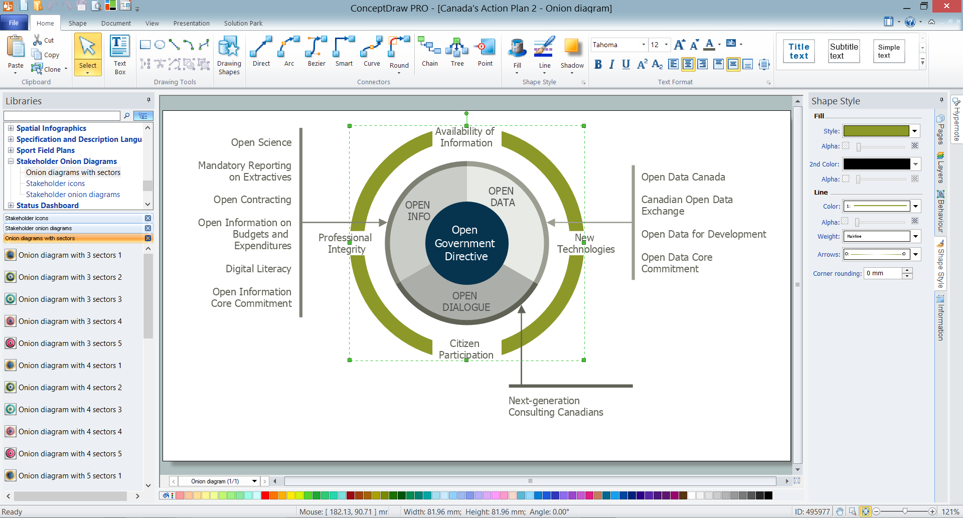
But how to create Onion Diagram? Now, it's very easy thanks to the ConceptDraw DIAGRAM diagramming and vector drawing software extended with Stakeholder Onion Diagrams Solution from the Management Area of ConceptDraw Solution Park.
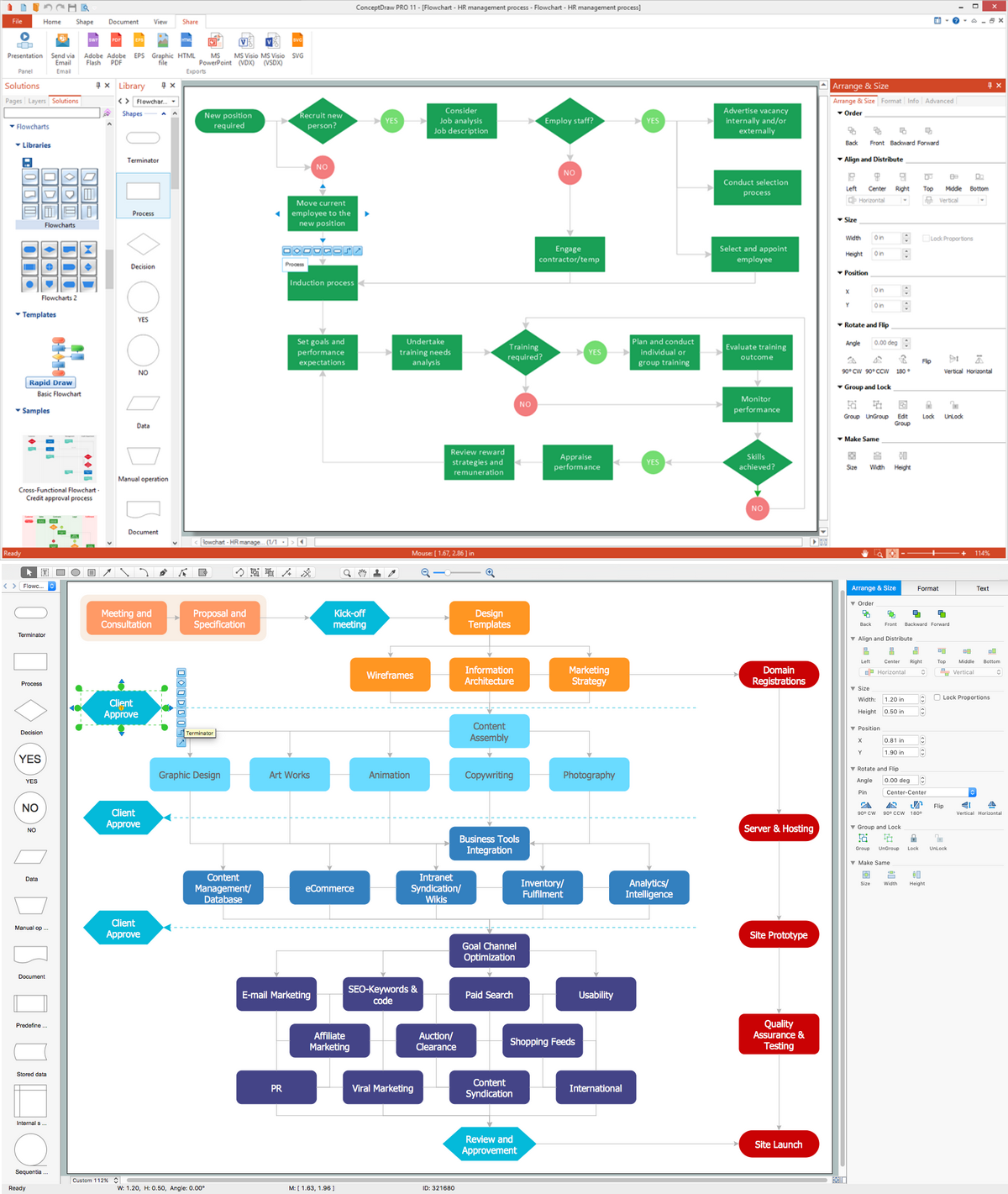
Flowcharting Software
IDEF1X Standard

Affinity Diagram Software
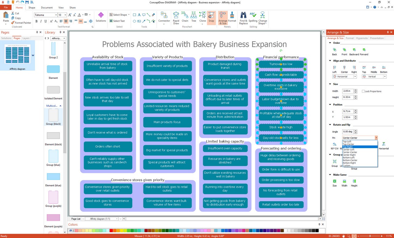
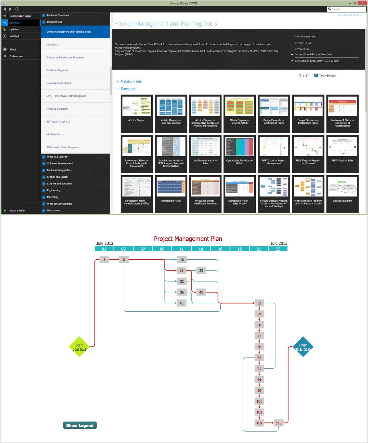
Seven Management and Planning Tools solution from the Business Productivity area of ConceptDraw Solution Park provides templates, samples and ready-to-use vector stencils that will help you design the professional looking Affinity Diagrams in a few moments.
Flowchart Programming Project. Flowchart Examples

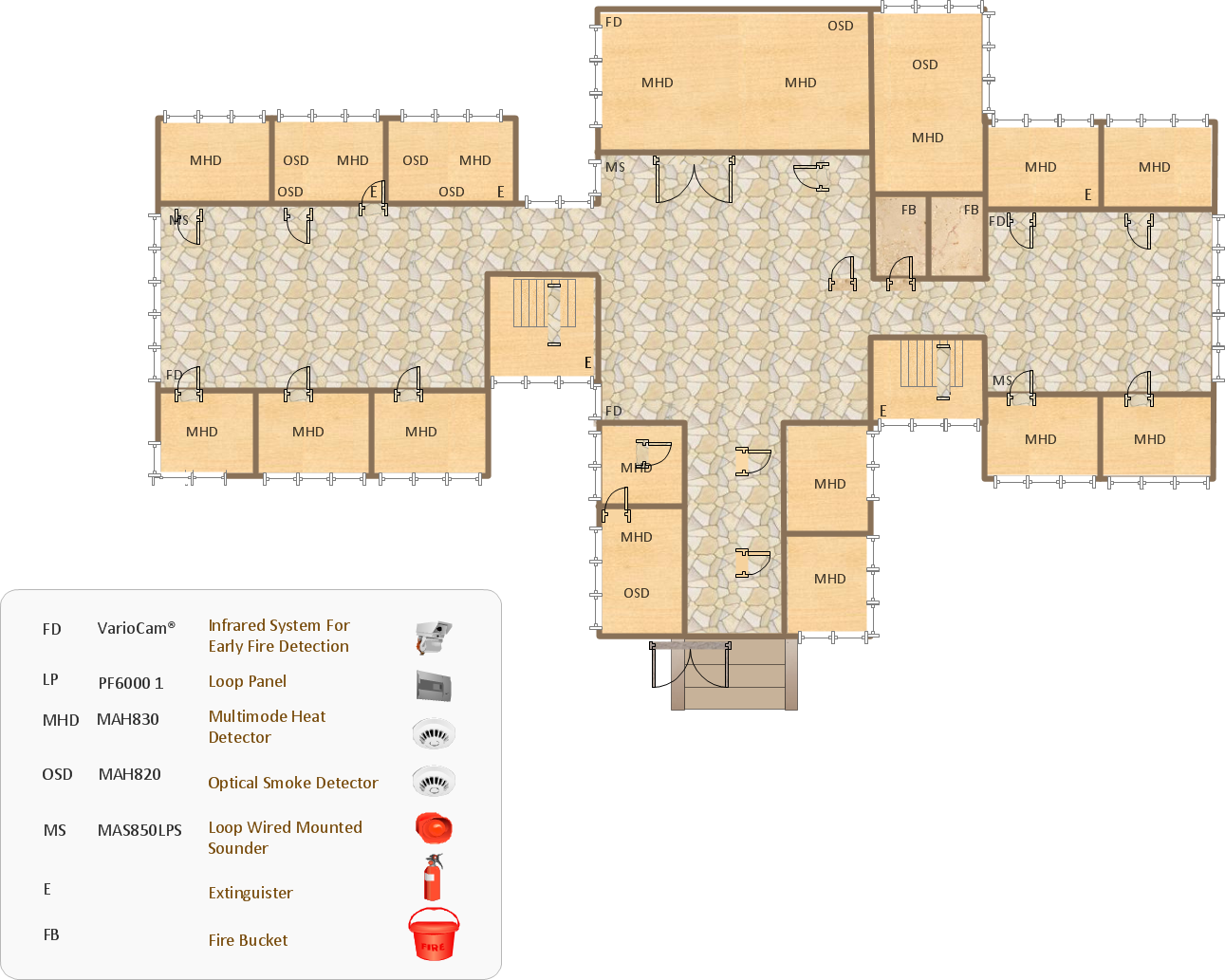
Emergency Action Plan Template
- Pert Chart For Online Recruitment System
- UML Class Diagram Example - Buildings and Rooms | Sentence ...
- Pert Explain In System Analysis And Design
- How to Discover Critical Path on a Gantt Chart | Critical Path Method ...
- Parking Management System Activitec
- Pert Chart For Online Food Ordering System
- Er Diagram Of Stock Management System
- Time Line Chart For Online Library Management System
- Activity Network ( PERT ) Chart | Activity Network Diagram Method ...
- Activities In A Project Management Software With Example Diagram
- ERD | Entity Relationship Diagrams, ERD Software for Mac and Win
- Flowchart | Basic Flowchart Symbols and Meaning
- Flowchart | Flowchart Design - Symbols, Shapes, Stencils and Icons
- Flowchart | Flow Chart Symbols
- Electrical | Electrical Drawing - Wiring and Circuits Schematics
- Flowchart | Common Flowchart Symbols
- Flowchart | Common Flowchart Symbols