Block Diagram Creator

Technical Drawing Software

ConceptDraw DIAGRAM extended with: Mechanical Engineering Solution, Electrical Engineering Solution, Chemical and Process Engineering Solution from the Industrial Engineering Area is powerful software for business and technical drawing. Its powerful drawing tools, predesigned vector objects, templates, samples are helpful for creation all kinds of Technical Drawings and Technical Diagrams, Electrical and Mechanical Schematics, Circuit and Wiring Diagrams, Structural Drawings, and many other.
Best Multi-Platform Diagram Software
CAD Drawing Software for Making Mechanic Diagram and Electrical Diagram Architectural Designs


The Best Drawing Program for Mac

Technical Drawing Software

 Electrical Engineering
This solution extends ConceptDraw DIAGRAM.9.5 (or later) with electrical engineering samples, electrical schematic symbols, electrical diagram symbols, templates and libraries of design elements, to help you design electrical schematics, digital and analog
Basic Diagramming


Electrical Symbols — Delay Elements

26 libraries of the Electrical Engineering Solution of ConceptDraw DIAGRAM make your electrical diagramming simple, efficient, and effective. You can simply and quickly drop the ready-to-use objects from libraries into your document to create the electrical diagram.
Electrical Symbols — Integrated Circuit

26 libraries of the Electrical Engineering Solution of ConceptDraw DIAGRAM make your electrical diagramming simple, efficient, and effective. You can simply and quickly drop the ready-to-use objects from libraries into your document to create the electrical diagram.
Process Flow Diagram

ConceptDraw DIAGRAM diagramming and vector drawing software extended with powerful tools of Flowcharts Solution from the "Diagrams" Area of ConceptDraw Solution Park is effective for drawing: Process Flow Diagram, Flow Process Diagram, Business Process Flow Diagrams.
Electrical Symbols — Electrical Circuits

Electrical and electronic circuits can be complicated. Making a drawing of the connections to all the component parts in the circuit's load makes it easier to understand how circuit components are connected. Drawings for electronic circuits are called "circuit diagrams". Drawings for electrical circuits are called "wiring diagrams".
26 libraries of the Electrical Engineering Solution of ConceptDraw DIAGRAM make your electrical diagramming simple, efficient, and effective. You can simply and quickly drop the ready-to-use objects from libraries into your document to create the electrical diagram.
ConceptDraw DIAGRAM Comparison with Omnigraffle Professional and MS Visio

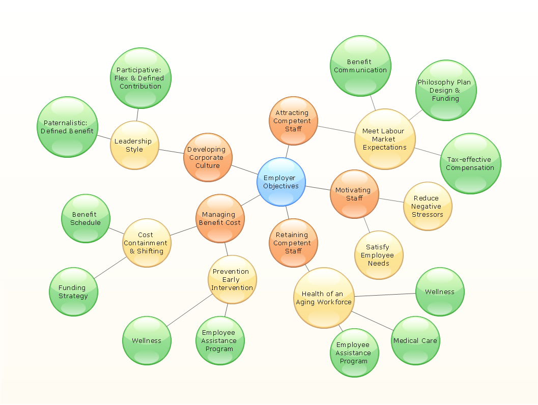
Bubble diagrams in Landscape Design with ConceptDraw DIAGRAM

Electrical Symbols — Inductors

26 libraries of the Electrical Engineering Solution of ConceptDraw DIAGRAM make your electrical diagramming simple, efficient, and effective. You can simply and quickly drop the ready-to-use objects from libraries into your document to create the electrical diagram.
- Pdf Block Diagram Electronic Mechanic
- CAD Drawing Software for Making Mechanic Diagram and Electrical ...
- Electrical Symbols, Electrical Diagram Symbols | Block Diagram ...
- CAD Drawing Software for Making Mechanic Diagram and Electrical ...
- Electronics Block Diagrams And Symbols Pdf
- Bubble Diagram In Architecture Pdf
- Electronic Mechanic Circuit Diagram Pdf
- Engineering Electronics Graphics Pdf
- Block Diagram Creator | Block Diagram | Electrical Symbols ...
- CAD Drawing Software for Making Mechanic Diagram and Electrical ...
- How To Convert a Bubble Diagram to an Adobe PDF Using ...
- CAD Drawing Software for Making Mechanic Diagram and Electrical ...
- CAD Drawing Software for Making Mechanic Diagram and Electrical ...
- CAD Drawing Software for Making Mechanic Diagram and Electrical ...
- Technical Drawing Software | Electrical Drawing Software and ...
- Electrical Electronics Drawing Pdf
- Electrical Symbols, Electrical Diagram Symbols | Local area network ...
- CAD Drawing Software for Making Mechanic Diagram and Electrical ...
- Bubbles And Schematic Diagram For Residential House Design Pdf
- Mechanical Engineering Symbol Pdf From Conceptdraw Com
- ERD | Entity Relationship Diagrams, ERD Software for Mac and Win
- Flowchart | Basic Flowchart Symbols and Meaning
- Flowchart | Flowchart Design - Symbols, Shapes, Stencils and Icons
- Flowchart | Flow Chart Symbols
- Electrical | Electrical Drawing - Wiring and Circuits Schematics
- Flowchart | Common Flowchart Symbols
- Flowchart | Common Flowchart Symbols