UML Package Diagram. Design Elements

ConceptDraw has 393 vector stencils in the 13 libraries that helps you to start using software for designing your own UML Diagrams. You can use the appropriate stencils of UML notation from UML Package library.
Diagramming Software for Design UML Package Diagrams


This vector stencils library contains 9 SysML symbols.
Use it to design your package diagrams using ConceptDraw PRO diagramming and vector drawing software.
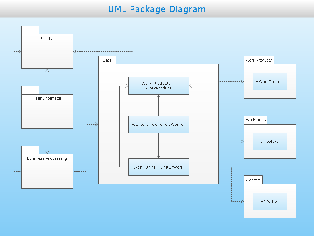
"A package diagram in the Unified Modeling Language depicts the dependencies between the packages that make up a model. ...
Elements
Package: a general purpose mechanism for organizing model elements & diagrams into groups. It provides an encapsulated namespace within which all the names must be unique. It is used to group semantically related elements. It is a namespace as well as an element that can be contained in other packages' namespaces.
Class: a representation of an object that reflects its structure and behavior within the system. It is a template from which running instances are created. Classes usually describe the logical structure of the system.
Interface: a specification of behavior. An implementation class must be written to support the behavior of an interface class.
Object: an instance of a class. It is often used in analysis to represent an artifact or other item.
Table: a stereotyped class." [Package diagram. Wikipedia]
The vector stencils library "Package diagram" is included in the SysML solution from the Software Development area of ConceptDraw Solution Park.
Use it to design your package diagrams using ConceptDraw PRO diagramming and vector drawing software.
"A package diagram in the Unified Modeling Language depicts the dependencies between the packages that make up a model. ...
Elements
Package: a general purpose mechanism for organizing model elements & diagrams into groups. It provides an encapsulated namespace within which all the names must be unique. It is used to group semantically related elements. It is a namespace as well as an element that can be contained in other packages' namespaces.
Class: a representation of an object that reflects its structure and behavior within the system. It is a template from which running instances are created. Classes usually describe the logical structure of the system.
Interface: a specification of behavior. An implementation class must be written to support the behavior of an interface class.
Object: an instance of a class. It is often used in analysis to represent an artifact or other item.
Table: a stereotyped class." [Package diagram. Wikipedia]
The vector stencils library "Package diagram" is included in the SysML solution from the Software Development area of ConceptDraw Solution Park.
Stereotype
Metaclass

Profile

Model library
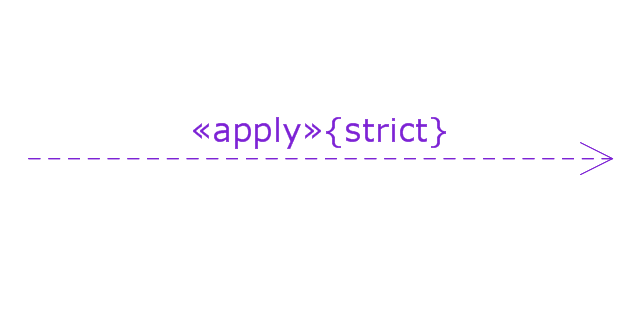
Extension path
Generalization path
Profile application
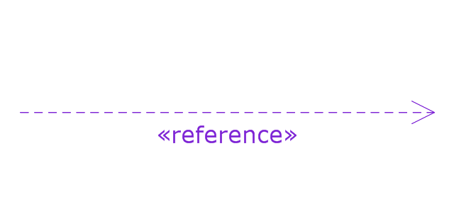
Metamodel reference
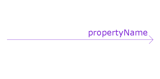
Unidirectional association
The vector stencils library "Bank UML package diagram" contains 5 shapes for drawing UML package diagrams.
Use it for object-oriented modeling of your bank information system.
"A package diagram in the Unified Modeling Language depicts the dependencies between the packages that make up a model.
In addition to the standard UML Dependency relationship, there are two special types of dependencies defined between packages:
* package import,
* package merge.
Elements.
1. Package: a general purpose mechanism for organizing model elements & diagrams into groups. It provides an encapsulated namespace within which all the names must be unique. It is used to group semantically related elements. It is a namespace as well as an element that can be contained in other packages' namespaces.
2. Class: a representation of an object that reflects its structure and behavior within the system. It is a template from which running instances are created. Classes usually describe the logical structure of the system.
3. Interface: a specification of behavior. An implementation class must be written to support the behavior of an interface class.
4. Object: an instance of a class. It is often used in analysis to represent an artifact or other item.
5. Table: a stereotyped class." [Package diagram. Wikipedia]
This example of UML package diagram symbols for the ConceptDraw PRO diagramming and vector drawing software is included in the ATM UML Diagrams solution from the Software Development area of ConceptDraw Solution Park.
UML package diagram symbols

The vector stencils library "UML package diagrams" contains 21 symbols for the ConceptDraw PRO diagramming and vector drawing software.
"A package diagram in the Unified Modeling Language depicts the dependencies between the packages that make up a model. ...
Elements.
(1) Package: It is a general purpose mechanism for organizing model elements & diagrams into groups. It provides an encapsulated namespace within which all the names must be unique. It is used to group semantically related elements. It is a namespace as well as an element that can be contained in other package's namespaces.
(2) Class: It is a representation of objects, that reflects their structure and behavior within the system. It is a template from which actually running instances are created. Classes usually describe logical structure of system.
(3) Interface: It is a specification of behavior. Implementing classes of an interface class are required to support the behavior.
(4) Object: It is an instance of class. It is often used in analysis to represent numerous artifacts and items that exist.
(5) Table: It is a stereotyped class." [Package diagram. Wikipedia]
The example "Design elements - UML package diagrams" is included in the Rapid UML solution from the Software Development area of ConceptDraw Solution Park.
UML package diagram symbols

Diagramming Software for Design UML Object Diagrams

ConceptDraw Rapid UML solution delivers libraries contain pre-designed objects fit UML notation, and ready to draw professional UML Object Diagram.
UML Deployment Diagram. Design Elements

ConceptDraw has 393 vector stencils in the 13 libraries that helps you to start using software for designing your own UML Diagrams. You can use the appropriate stencils of UML notation from UML Deployment library.
UML Collaboration Diagram. Design Elements

ConceptDraw has 393 vector stencils in the 13 libraries that helps you to start using software for designing your own UML Diagrams. You can use the appropriate stencils of UML notation from UML Collaboration library with 36 objects
SysML

ConceptDraw DIAGRAM diagramming and vector drawing software was extended with SysML Solution from the Software Development Area of ConceptDraw Solution Park specially to help systems engineers design various model systems with SysML.
Banking System

UML Composite Structure Diagram. Design Elements

ConceptDraw has 393 vector stencils in the 13 libraries that helps you to start using software for designing your own UML Diagrams. You can use the appropriate stencils of UML notation from UML Composite Structure library.
UML Flowchart Symbols

The Rapid UML solution for ConceptDraw DIAGRAM software offers diversity of UML flowchart symbols for drawing all types of UML diagrams.
UML Notation

Two types of diagrams are used in UML: Structure Diagrams and Behavior Diagrams. Behavior Diagrams represent the processes proceeding in a modeled environment. Structure Diagrams represent the elements that compose the system.
This bank account UML package diagram was redesigned from the Wikimedia Commons file: Package diagram1.jpg.
[commons.wikimedia.org/ wiki/ File:Package_ diagram1.jpg]
This file is licensed under the Creative Commons Attribution-Share Alike 3.0 Unported license. [creativecommons.org/ licenses/ by-sa/ 3.0/ deed.en]
"A very important concept in object-oriented design, inheritance, refers to the ability of one class (child class) to inherit the identical functionality of another class (super class), and then add new functionality of its own. (In a very non-technical sense, imagine that I inherited my mother's general musical abilities, but in my family I'm the only one who plays electric guitar.) To model inheritance on a class diagram, a solid line is drawn from the child class (the class inheriting the behavior) with a closed, unfilled arrowhead (or triangle) pointing to the super class. Consider types of bank accounts: Figure 4 shows how both CheckingAccount and SavingsAccount classes inherit from the BankAccount class.
Figure 4: Inheritance is indicated by a solid line with a closed, unfilled arrowhead pointing at the super class." [ibm.com/ developerworks/ rational/ library/ content/ RationalEdge/ sep04/ bell/ index.html]
This bank account UML package diagram example was created using the ConceptDraw PRO diagramming and vector drawing software extended with the ATM UML Diagrams solution from the Software Development area of ConceptDraw Solution Park.
Bank account UML package diagram

- Package Diagram For Library System
- UML Package Diagram . Design Elements | Diagramming Software ...
- Diagramming Software for Design UML Package Diagrams | UML ...
- Package Diagram For Library Management System
- Package Diagram For Library Management System Pdf
- Uml Package Diagram In Library Management System
- Package Diagram For Library Management System In Uml
- Show The Package Diagram In Library Management System
- Package Diagram Library Management System
- Library Management System Package Diagram
- Package Diagram For Library Management In Case Tools
- UML Package Diagram . Design Elements | Quality Management ...
- Component Diagram For Library Management System In Uml
- Vector stencils library - Package diagram | Road transport - Vector ...
- Library System Package Diagram
- UML Package Diagram . Design Elements | Diagramming Software ...
- Vector stencils library - Package diagram
- UML package diagram for Bank account | Bank UML Diagram ...
- UML Package Diagram . Design Elements | UML Deployment ...
- Composite Diagram For Library Management System
- ERD | Entity Relationship Diagrams, ERD Software for Mac and Win
- Flowchart | Basic Flowchart Symbols and Meaning
- Flowchart | Flowchart Design - Symbols, Shapes, Stencils and Icons
- Flowchart | Flow Chart Symbols
- Electrical | Electrical Drawing - Wiring and Circuits Schematics
- Flowchart | Common Flowchart Symbols
- Flowchart | Common Flowchart Symbols