Network Printer


The vector stencils library "Network layout floorplan" contain 34 symbol icons for drawing computer network floor plans and communication equipment and cabling layouts.
"Networking hardware may also be known as network equipment or computer networking devices. Units which are the last receiver or generate data are called hosts or data terminal equipment.
All these terms refer to devices facilitating the use of a computer network. Specifically, they mediate data in a computer network. ...
Typically, networking hardware includes gateways, routers, network bridges, switches, hubs, and repeaters. But it also includes hybrid network devices such as multilayer switches, protocol converters, bridge routers, proxy servers, firewalls, network address translators, multiplexers, network interface controllers, wireless network interface controllers, modems, ISDN terminal adapters, line drivers, wireless access points, networking cables and other related hardware.
The most common kind of networking hardware today is a copper-based Ethernet adapter because of its standard inclusion on most modern computer systems. Wireless networking has, however, become increasingly popular, especially for portable and handheld devices.
Other hardware prevalent in computer networking includes data center equipment (such as file servers, database servers and storage areas), network services (such as DNS, DHCP, email, etc.) as well as devices which assure content delivery." [Networking hardware. Wikipedia]
The shapes example "Design elements - Network layout floorplan" was created using the ConceptDraw PRO diagramming and vector drawing software extended with the Network Layout Floor Plans solution from the Computer and Networks area of ConceptDraw Solution Park.
Network layout floor plan symbols

Network Gateway Router

Special libraries of highly detailed, accurate shapes and computer graphics, servers, hubs, switches, printers, mainframes, face plates, routers etc.
Network Layout

The vector stencils library "Cisco network topology" contains 89 symbols of Cisco network devices and design elements for drawing computer network topology diagrams.
"There are two basic categories of network topologies:
(1) Physical topologies,
(2) Logical topologies.
The shape of the cabling layout used to link devices is called the physical topology of the network. This refers to the layout of cabling, the locations of nodes, and the interconnections between the nodes and the cabling. The physical topology of a network is determined by the capabilities of the network access devices and media, the level of control or fault tolerance desired, and the cost associated with cabling or telecommunications circuits.
The logical topology in contrast, is the way that the signals act on the network media, or the way that the data passes through the network from one device to the next without regard to the physical interconnection of the devices." [Network topology. Wikipedia]
The symbols example "Cisco network topology - Vector stencils library" was created using the ConceptDraw PRO diagramming and vector drawing software extended with the Cisco Network Diagrams solution from the Computer and Networks area of ConceptDraw Solution Park.
www.conceptdraw.com/ solution-park/ computer-networks-cisco
Router

Broadband router

Router firewall

Wireless router

Workgroup switch

ATM switch

ISDN switch

Multilayer switch

Protocol translator

Communications server

Transpath

Bridge

Terminal server

Route switch processor

Content engine (cache director)
-cisco-network-topology---vector-stencils-library.png--diagram-flowchart-example.png)
Management engine (ME 1100)
-cisco-network-topology---vector-stencils-library.png--diagram-flowchart-example.png)
Switch processor

ITP

Voice gateway

BBSM

ATA

SIP Proxy server

NetRanger

Cisco 1000

IP

System controller

ACE

Directory server

ADM

Cisco Unity Express

Unity server

Cisco security

CallManager

DSLAM

H.323

CDM (Content Distribution Manager)
-cisco-network-topology---vector-stencils-library.png--diagram-flowchart-example.png)
ICM

Access point

Wireless bridge

Wireless connectivity

Guard

Mobile access router

Carrier Routing System (CRS)
-cisco-network-topology---vector-stencils-library.png--diagram-flowchart-example.png)
Vault

Workstation

PC

Macintosh

Cloud, gold

Cloud, white

Cloud, standard color

Cisco security management

PBX

DPT

Government building

Headquarters, blue

Router in building

Man

Woman

Workgroup switch, subdued

Router, subdued

File server

Firewall, horizontal

Firewall, vertical

Firewall, vertical, subdued

Lock

Key

Lock and key

Car

Truck

File cabinet

Breakout box

Breakout box, blue

Host

Relational database

Modem

BBS (Bulletin Board System)
-cisco-network-topology---vector-stencils-library.png--diagram-flowchart-example.png)
Satellite

Satellite dish

UPS

RPS

MAU

PAD

PAD X.28

Diskette

Contact center

Page icon
Antenna

Antenna, blue

Radio tower

Network Hubs

How To use Switches in Network Diagram

Use ConceptDraw DIAGRAM with Computer & Networks solution for drawing LAN and WAN topology and configuration diagrams, Cisco network diagrams, network wiring schemes and floor plan layouts.
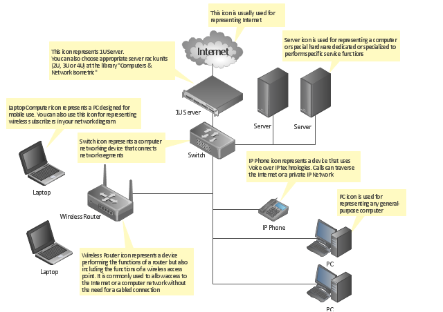
"A computer network diagram is a schematic depicting the nodes and connections amongst nodes in a computer network or, more generally, any telecommunications network. ...
Readily identifiable icons are used to depict common network appliances e.g. Router, and the style of lines between them indicate the type of connection. Clouds are used to represent networks external to the one pictured for the purposes of depicting connections between internal and external devices, without indicating the specifics of the outside network. ...
At different scales diagrams may represent various levels of network granularity. At the LAN level, individual nodes may represent individual physical devices, such as hubs or file servers, while at the WAN level, individual nodes may represent entire cities. In addition, when the scope of a diagram crosses the common LAN/ MAN/ WAN boundaries, representative hypothetical devices may be depicted instead of showing all actually existing nodes." [Computer network diagram. Wikipedia]
The computer network diagram template for the ConceptDraw PRO diagramming and vector drawing software is included in the Computer and Networks solution from the Computer and Networks area of ConceptDraw Solution Park.
Computer network diagram template
- Lan Router Server Network Diagram
- Router Switch And A Server In A Rack Diagram
- Star Network Topology | Fully Connected Network Topology ...
- Computer Router Switch Diagram
- Network Diagram Including Workstation Switch Server Router
- How To use Switches in Network Diagram | VMware vNetwork ...
- Network Gateway Router | Computer network - Vector stencils library ...
- Rack diagram - Template | How To use Switches in Network ...
- Network Layout Floor Plans | Network Layout | Design elements ...
- A Network Diagram Workstation Switch Server Router Firewall
- Network hardware - Vector stencils library | Network layout floorplan ...
- How To use Switches in Network Diagram | Cisco Switches and ...
- Computer Network Diagrams | Network Gateway Router | Fully ...
- Network Layout Floor Plans | Design elements - Network layout ...
- Logical network topology diagram | Network Diagram Software ...
- How To use Switches in Network Diagram | Network Layout | Star ...
- Network Printer | Network Diagram Software | Network diagrams ...
- Router Switch Computer Networking Layout
- Network Glossary Definition | Network hardware - Vector stencils ...
- How To use Switches in Network Diagram | Cisco Network ...
- ERD | Entity Relationship Diagrams, ERD Software for Mac and Win
- Flowchart | Basic Flowchart Symbols and Meaning
- Flowchart | Flowchart Design - Symbols, Shapes, Stencils and Icons
- Flowchart | Flow Chart Symbols
- Electrical | Electrical Drawing - Wiring and Circuits Schematics
- Flowchart | Common Flowchart Symbols
- Flowchart | Common Flowchart Symbols