Multiprotocol Label Switching (MPLS). Computer and Network Examples

ConceptDraw DIAGRAM is a powerful network diagramming and vector drawing software that provides the Computer and Networks solution with wide set of ready-to-use predesigned vector stencils and examples to help you design the MPLS Networks quick and easy.

VMware vNetwork Distributied Switch (vDS). Computer and Network Examples
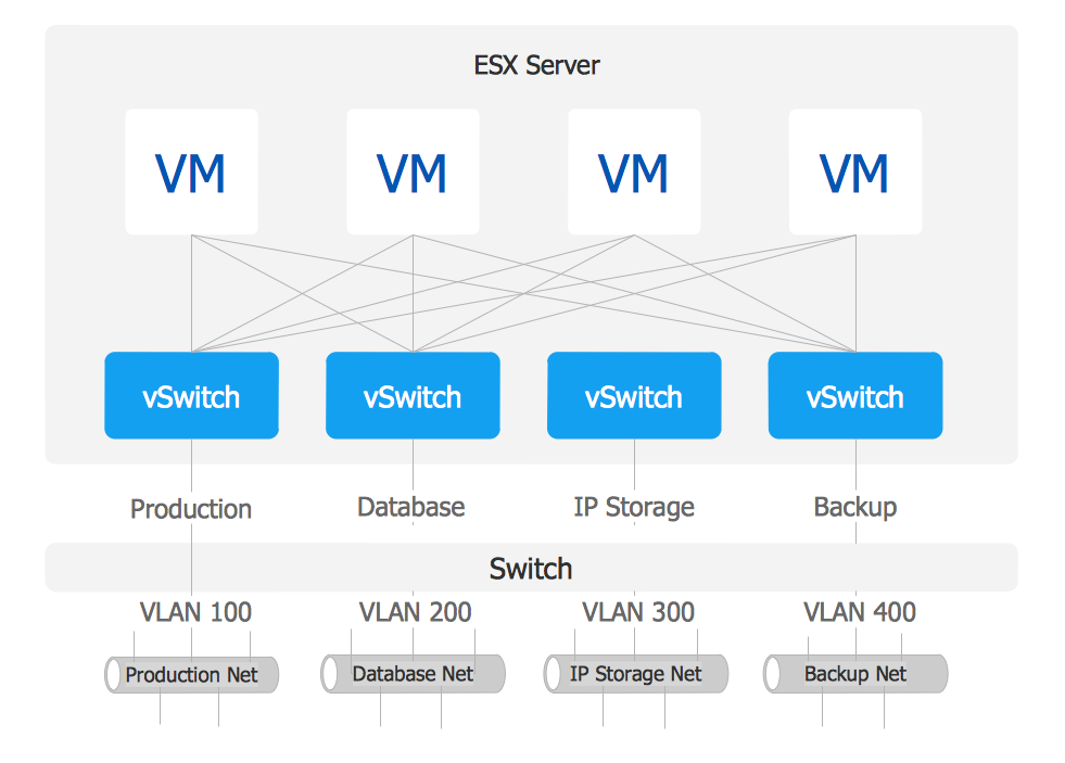
This example was created in ConceptDraw DIAGRAM using the Computer and Networks Area of ConceptDraw Solution Park and shows the VMware vDS network diagram.
Cisco Switches and Hubs. Cisco icons, shapes, stencils and symbols

Diagram of a Basic Computer Network. Computer Network Diagram Example

This sample shows the connection scheme of the home WLAN equipment to the Internet.
The vector stencils library "Cisco WAN" contains 15 symbols of wide area network (WAN) devices and equipment for drawing Cisco WAN diagrams.
"A wide area network (WAN) is a network that covers a broad area (i.e., any telecommunications network that links across metropolitan, regional, or national boundaries) using leased telecommunication lines. Business and government entities utilize WANs to relay data among employees, clients, buyers, and suppliers from various geographical locations. ...
Related terms for other types of networks are personal area networks (PANs), local area networks (LANs), campus area networks (CANs), or metropolitan area networks (MANs) which are usually limited to a room, building, campus or specific metropolitan area (e.g., a city) respectively.
... it may be best to view WANs as computer networking technologies used to transmit data over long distances, and between different LANs, MANs and other localised computer networking architectures. ...
WANs are often built using leased lines. At each end of the leased line, a router connects the LAN on one side with a second router within the LAN on the other. Leased lines can be very expensive. Instead of using leased lines, WANs can also be built using less costly circuit switching or packet switching methods. Network protocols including TCP/ IP deliver transport and addressing functions. Protocols including Packet over SONET/ SDH, MPLS, ATM and Frame relay are often used by service providers to deliver the links that are used in WANs." [Wide area network. Wikipedia]
The symbols example "Cisco WAN - Vector stencils library" was created using the ConceptDraw PRO diagramming and vector drawing software extended with the Cisco Network Diagrams solution from the Computer and Networks area of ConceptDraw Solution Park.
www.conceptdraw.com/ solution-park/ computer-networks-cisco
CSU/DSU
WAN
MUX
PBX switch
Hub
Hub, blue
NAT

Network cloud, dark
Network cloud, gold
Network cloud, white
Network cloud, standard color
Distributed director
Local director
PBX
DPT
Network Topologies


Building Drawing. Design Element — Plumbing

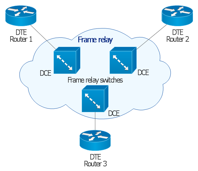
This Cisco network diagram example was redesigned from the Wikimedia Commons file: Frame relay.jpg. [commons.wikimedia.org/ wiki/ File:Frame_ relay.jpg]
This example depicts basic network diagram of a frame relay network.
"Frame relay is a standardized wide area network technology that specifies the physical and logical link layers of digital telecommunications channels using a packet switching methodology. Originally designed for transport across Integrated Services Digital Network (ISDN) infrastructure, it may be used today in the context of many other network interfaces.
Network providers commonly implement frame relay for voice (VoFR) and data as an encapsulation technique, used between local area networks (LANs) over a wide area network (WAN). Each end-user gets a private line (or leased line) to a frame relay node. The frame relay network handles the transmission over a frequently changing path transparent to all end-user extensively used WAN protocols. It is less expensive than leased lines and that is one reason for its popularity. The extreme simplicity of configuring user equipment in a frame relay network offers another reason for frame relay's popularity.
With the advent of Ethernet over fiber optics, MPLS, VPN and dedicated broadband services such as cable modem and DSL, the end may loom for the frame relay protocol and encapsulation. However many rural areas remain lacking DSL and cable modem services. In such cases, the least expensive type of non-dial-up connection remains a 64-kbit/ s frame relay line. Thus a retail chain, for instance, may use frame relay for connecting rural stores into their corporate WAN." [Frame Relay. Wikipedia]
The Cisco network diagram example "Frame relay" was created using the ConceptDraw PRO diagramming and vector drawing software extended with the Cisco Network Diagrams solution from the Computer and Networks area of ConceptDraw Solution Park.
Cisco network diagram
Virtual private networks (VPN). Computer and Network Examples

This example was created in ConceptDraw DIAGRAM using the Computer and Networks Area of ConceptDraw Solution Park and shows the Virtual Private Network (VPN) diagram.
"In computer networking, cloud computing is computing that involves a large number of computers connected through a communication network such as the Internet, similar to utility computing. ...
Network-based services, which appear to be provided by real server hardware, and are in fact served up by virtual hardware, simulated by software running on one or more real machines are often called cloud computing. Such virtual servers do not physically exist and can therefore be moved around and scaled up or down on the fly without affecting the end user, somewhat like a cloud becoming larger or smaller without being a physical object. ...
Typically, the seller has actual energy-consuming servers which host products and services from a remote location, so end-users don't have to; they can simply log on to the network without installing anything. The major models of cloud computing service are known as software as a service, platform as a service, and infrastructure as a service. These cloud services may be offered in a public, private or hybrid network. Google, Amazon,leadsquared.com, Oracle Cloud, Salesforce, Zoho, Access2MyPC, and Microsoft Azure are some well-known cloud vendors." [Cloud computing. Wikipedia]
The AWS architecture diagram example "2-Tier Auto-scalable Web Application Architecture in 1 AZ" was created using the ConceptDraw PRO diagramming and vector drawing software extended with the AWS Architecture Diagrams solution from the Computer and Networks area of ConceptDraw Solution Park.
AWS architecture diagram
.png--diagram-flowchart-example.png)
- Frame Cloud Png
- Mpls Cloud Visio Stencil
- Network Diagram Examples | Stakeholder Onion Diagrams | Cisco ...
- Multiprotocol Label Switching ( MPLS ). Computer and Network ...
- Network Pipe Icon Png
- Mpls Lines Connection Diagram
- Cloud Computing Architecture Diagrams | Internet Connectivity ...
- How to Build Cloud Computing Diagram Principal Cloud ...
- Cloud Computing Architecture Diagrams | Cisco WAN. Cisco icons ...
- Cisco Network Templates | Network Diagram Examples | How To ...
- ERD | Entity Relationship Diagrams, ERD Software for Mac and Win
- Flowchart | Basic Flowchart Symbols and Meaning
- Flowchart | Flowchart Design - Symbols, Shapes, Stencils and Icons
- Flowchart | Flow Chart Symbols
- Electrical | Electrical Drawing - Wiring and Circuits Schematics
- Flowchart | Common Flowchart Symbols
- Flowchart | Common Flowchart Symbols