The vector stencils library "Cisco network topology" contains 89 symbols of Cisco network devices and design elements for drawing computer network topology diagrams.
"There are two basic categories of network topologies:
(1) Physical topologies,
(2) Logical topologies.
The shape of the cabling layout used to link devices is called the physical topology of the network. This refers to the layout of cabling, the locations of nodes, and the interconnections between the nodes and the cabling. The physical topology of a network is determined by the capabilities of the network access devices and media, the level of control or fault tolerance desired, and the cost associated with cabling or telecommunications circuits.
The logical topology in contrast, is the way that the signals act on the network media, or the way that the data passes through the network from one device to the next without regard to the physical interconnection of the devices." [Network topology. Wikipedia]
The symbols example "Cisco network topology - Vector stencils library" was created using the ConceptDraw PRO diagramming and vector drawing software extended with the Cisco Network Diagrams solution from the Computer and Networks area of ConceptDraw Solution Park.
www.conceptdraw.com/ solution-park/ computer-networks-cisco
Router

Broadband router

Router firewall

Wireless router

Workgroup switch

ATM switch

ISDN switch

Multilayer switch

Protocol translator

Communications server

Transpath

Bridge

Terminal server

Route switch processor

Content engine (cache director)
-cisco-network-topology---vector-stencils-library.png--diagram-flowchart-example.png)
Management engine (ME 1100)
-cisco-network-topology---vector-stencils-library.png--diagram-flowchart-example.png)
Switch processor

ITP

Voice gateway

BBSM

ATA

SIP Proxy server

NetRanger

Cisco 1000

IP

System controller

ACE

Directory server

ADM

Cisco Unity Express

Unity server

Cisco security

CallManager

DSLAM

H.323

CDM (Content Distribution Manager)
-cisco-network-topology---vector-stencils-library.png--diagram-flowchart-example.png)
ICM

Access point

Wireless bridge

Wireless connectivity

Guard

Mobile access router

Carrier Routing System (CRS)
-cisco-network-topology---vector-stencils-library.png--diagram-flowchart-example.png)
Vault

Workstation

PC

Macintosh

Cloud, gold

Cloud, white

Cloud, standard color

Cisco security management

PBX

DPT

Government building

Headquarters, blue

Router in building

Man

Woman

Workgroup switch, subdued

Router, subdued

File server

Firewall, horizontal

Firewall, vertical

Firewall, vertical, subdued

Lock

Key

Lock and key

Car

Truck

File cabinet

Breakout box

Breakout box, blue

Host

Relational database

Modem

BBS (Bulletin Board System)
-cisco-network-topology---vector-stencils-library.png--diagram-flowchart-example.png)
Satellite

Satellite dish

UPS

RPS

MAU

PAD

PAD X.28

Diskette

Contact center

Page icon
Antenna

Antenna, blue

Radio tower

Cisco Network Topology. Cisco icons, shapes, stencils and symbols

Any Cisco equipment on the network are named like node. Network diagram topology commonly designed within connected nodes. Cisco icons are worldwide acknowledged and mainly established as standard icons for network diagrams. You may use them loosely, but you may not rework them.
The Cisco Network Diagram shows how signals act on the networked devices, or how data routes on the network from one device to the other. There are number of physical network typologies that engineers use while constructing computer networks.
Cisco Routers. Cisco icons, shapes, stencils and symbols

Any planning begins with an analysis of the business requirements to the final system. Basic network parameters, which should be assessed are the scalability, accessibility, cost, speed and safety.
Speed and cost are often mistaken for the most important parameters, and the rest of the parameters aren't even remembered. This is not entirely correct. Initially, it is necessary to assess the business plans for the future, because sometimes it is more profitable to invest more money in the beginning. If the business is to develop, then, consequently, demands on
The vector stencils library "Cisco LAN" contains 23 symbols of local area network (LAN) devices and equipment for drawing Cisco LAN topology diagrams.
"Network topology describes the layout of interconnections between devices and network segments. At the Data Link Layer and Physical Layer, a wide variety of LAN topologies have been used, including ring, bus, mesh and star, but the most common LAN topology in use today is switched Ethernet. At the higher layers, the Internet Protocol (TCP/ IP) has become the standard, replacing NetBEUI, IPX/ SPX, AppleTalk and others.
Simple LANs generally consist of one or more switches. A switch can be connected to a router, cable modem, or ADSL modem for Internet access. Complex LANs are characterized by their use of redundant links with switches using the spanning tree protocol to prevent loops, their ability to manage differing traffic types via quality of service (QoS), and to segregate traffic with VLANs. A LAN can include a wide variety of network devices such as switches, firewalls, routers, load balancers, and sensors.
LANs can maintain connections with other LANs via leased lines, leased services, or the Internet using virtual private network technologies. Depending on how the connections are established and secured in a LAN, and the distance involved, a LAN may also be classified as a metropolitan area network (MAN) or a wide area network (WAN)." [Local area network. Wikipedia]
The symbols example "Cisco LAN - Vector stencils library" was created using the ConceptDraw PRO diagramming and vector drawing software extended with the Cisco Network Diagrams solution from the Computer and Networks area of ConceptDraw Solution Park.
www.conceptdraw.com/ solution-park/ computer-networks-cisco
Sun workstation

Workstation

PC

Macintosh

Terminal

Mini VAX

Printer

Laptop

File server

Monitor

Web cluster

ATM fast gigabit etherswitch

HP Mini

Supercomputer

LAN2LAN

LAN to LAN

Web server

Web browser

Repeater

PDA

General appliance

PC, blue

Mini VAX, blue

The vector stencils library "Cisco network topology" contains 89 symbols of Cisco network devices and design elements for drawing computer network topology diagrams.
"There are two basic categories of network topologies:
(1) Physical topologies,
(2) Logical topologies.
The shape of the cabling layout used to link devices is called the physical topology of the network. This refers to the layout of cabling, the locations of nodes, and the interconnections between the nodes and the cabling. The physical topology of a network is determined by the capabilities of the network access devices and media, the level of control or fault tolerance desired, and the cost associated with cabling or telecommunications circuits.
The logical topology in contrast, is the way that the signals act on the network media, or the way that the data passes through the network from one device to the next without regard to the physical interconnection of the devices." [Network topology. Wikipedia]
The symbols example "Cisco network topology - Vector stencils library" was created using the ConceptDraw PRO diagramming and vector drawing software extended with the Cisco Network Diagrams solution from the Computer and Networks area of ConceptDraw Solution Park.
www.conceptdraw.com/ solution-park/ computer-networks-cisco
"There are two basic categories of network topologies:
(1) Physical topologies,
(2) Logical topologies.
The shape of the cabling layout used to link devices is called the physical topology of the network. This refers to the layout of cabling, the locations of nodes, and the interconnections between the nodes and the cabling. The physical topology of a network is determined by the capabilities of the network access devices and media, the level of control or fault tolerance desired, and the cost associated with cabling or telecommunications circuits.
The logical topology in contrast, is the way that the signals act on the network media, or the way that the data passes through the network from one device to the next without regard to the physical interconnection of the devices." [Network topology. Wikipedia]
The symbols example "Cisco network topology - Vector stencils library" was created using the ConceptDraw PRO diagramming and vector drawing software extended with the Cisco Network Diagrams solution from the Computer and Networks area of ConceptDraw Solution Park.
www.conceptdraw.com/ solution-park/ computer-networks-cisco
Router
Broadband router
Router firewall
Wireless router
Workgroup switch
ATM switch
ISDN switch
Multilayer switch
Protocol translator
Communications server
Transpath
Bridge
Terminal server
Route switch processor
Content engine (cache director)
Management engine (ME 1100)
Switch processor
ITP
Voice gateway
BBSM
ATA
SIP Proxy server
NetRanger
Cisco 1000
IP
System controller
ACE
Directory server
ADM
Cisco Unity Express
Unity server
Cisco security
CallManager
DSLAM
H.323
CDM (Content Distribution Manager)
ICM
Access point
Wireless bridge
Wireless connectivity
Guard
Mobile access router
Carrier Routing System (CRS)
Vault
Workstation
PC
Macintosh
Cloud, gold
Cloud, white
Cloud, standard color
Cisco security management
PBX
DPT
Government building
Headquarters, blue
Router in building
Man
Woman
Workgroup switch, subdued
Router, subdued
File server
Firewall, horizontal
Firewall, vertical
Firewall, vertical, subdued
Lock
Key
Lock and key
Car
Truck
File cabinet
Breakout box
Breakout box, blue
Host
Relational database
Modem
BBS (Bulletin Board System)
Satellite
Satellite dish
UPS
RPS
MAU
PAD
PAD X.28
Diskette
Contact center
Page icon
Antenna
Antenna, blue
Radio tower
How To use Switches in Network Diagram

Use ConceptDraw DIAGRAM with Computer & Networks solution for drawing LAN and WAN topology and configuration diagrams, Cisco network diagrams, network wiring schemes and floor plan layouts.

Network Glossary Definition

Easy to draw network topology diagrams, network mapping and Cisco network topology.
The vector stencils library "Computer network" contains 51 symbols of computer network devices and equipment for drawing computer network diagrams.
"Network Mapping Software.
A number of software tools exist to design computer network diagrams / or generate visual maps of networks, servers, storage, services, data centers, and other peripherals. Broadly, there are two types of software tools - those that help create diagrams manually and those that generate them using automated / semi-automated approaches.
Type of Software.
(1) Manual - allows users to design and draw logical and physical topology diagrams by manually placing icons and connections.
(2) Automated - generate topology diagrams / maps by traversing the network and automatically discovering resident devices or by importing network data." [Comparison of network diagram software. Wikipedia]
ConceptDraw PRO is the software for manual design of computer network diagrams. The solutions of the Computer and Networks area in ConceptDraw Solution Park extend ConceptDraw PRO with vector stencils libraries, templates and examples for creating the computer network diagrams.
The symbols example "Computer network - Vector stencils library" was created using the ConceptDraw PRO diagramming and vector drawing software extended with the Computer and Networks solution from the Computer and Networks area of ConceptDraw Solution Park.
www.conceptdraw.com/ solution-park/ computer-and-networks
Laptop

Desktop computer

Firewall

Bus

Ethernet

Star network

FDDI Ring

Token-ring

Comm-link

Modem

Laser printer

Inkjet printer

Image scanner

City

Ethernet hub

Wireless router

Network switch

iPod Classic

iPhone/ iPod Touch

Xserve RAID

XServe

Apple Thunderbolt Display

Data store

Mac Pro

iMac

RAID

Mainframe

Rack-mountable server

Server

PDA

Cloud

Computer monitor

Workstation

Router

IP Phone

Fax

Mobile phone

Smartphone

Compact Disk

Mouse

Apple Wireless Mouse

Computer keyboard

Apple Keyboard

Radio tower

Satellite dish

Satellite

Webcam

AirPort Extreme

Airport Express

MacBook

iPhone 4

The vector stencils library "Network hardware" contains 27 clipart images and symbols of network equipment for drawing computer network diagrams.
"Networking hardware may also be known as network equipment or computer networking devices. Units which are the last receiver or generate data are called hosts or data terminal equipment.
All these terms refer to devices facilitating the use of a computer network. Specifically, they mediate data in a computer network. ...
Typically, networking hardware includes gateways, routers, network bridges, switches, hubs, and repeaters. But it also includes hybrid network devices such as multilayer switches, protocol converters, bridge routers, proxy servers, firewalls, network address translators, multiplexers, network interface controllers, wireless network interface controllers, modems, ISDN terminal adapters, line drivers, wireless access points, networking cables and other related hardware.
The most common kind of networking hardware today is a copper-based Ethernet adapter because of its standard inclusion on most modern computer systems. Wireless networking has, however, become increasingly popular, especially for portable and handheld devices.
Other hardware prevalent in computer networking includes data center equipment (such as file servers, database servers and storage areas), network services (such as DNS, DHCP, email, etc.) as well as devices which assure content delivery.
Taking a wider view, mobile phones, PDAs and even modern coffee machines may also be considered networking hardware. As technology advances and IP-based networks are integrated into building infrastructure and household utilities, network hardware will becomes an ambiguous term owing to the vastly increasing number of "network capable" endpoints." [Networking hardware. Wikipedia]
The clip art example "Network hardware -Vector stencils library" was created using the ConceptDraw PRO diagramming and vector drawing software extended with the Computer and Networks solution from the Computer and Networks area of ConceptDraw Solution Park.
www.conceptdraw.com/ solution-park/ computer-and-networks
Rack
Patch Panel 48
Modem
Switch
Hub

Router
AirPort Extreme
Xserve RAID
Server
Server
RAID Drive
Patch bay
UPS
Airport Express
Wireless router
ADSL modem
Mac Pro
Power Mac G5
Power Mac G4 Cube
XServe
Patch Panel 24
AirPort Extreme/ Time Capsule
Switch (8 port)
-network-hardware---vector-stencils-library.png--diagram-flowchart-example.png)
Switch (16 port)
-network-hardware---vector-stencils-library.png--diagram-flowchart-example.png)
Switch (24 port)
-network-hardware---vector-stencils-library.png--diagram-flowchart-example.png)
Switch (48 port)
-network-hardware---vector-stencils-library.png--diagram-flowchart-example.png)
Patch Panel (24 port)
-network-hardware---vector-stencils-library.png--diagram-flowchart-example.png)
Cisco Network Templates

ConceptDraw has Cisco network diagram templates:
Wireless Mesh Network, Network Organization Chart, Roaming Wireless Local Area Network, Cisco ISG Topology Diagram, Cisco Express Forwarding Sample that facilitates drawing at the initial stage.
However for customizing Cisco network diagrams you can use 13 Libraries like this: Cisco Basic, Cisco Buildings, Cisco IBM, Cisco LAN, Cisco WAN, Cisco Media, Cisco Optical, Cisco People, Cisco Routers, Cisco Security, Cisco Switches&Hub, Cisco Telepresences, etc.
This take great advantage to you for designing Cisco network diagram templates.
"Network planning and design is an iterative process, encompassing topological design, network-synthesis, and network-realization, and is aimed at ensuring that a new telecommunications network or service meets the needs of the subscriber and operator. Network planning process involves three main steps: 1) Topological design: This stage involves determining where to place the components and how to connect them. 2) Network-synthesis: This stage involves determining the size of the components used, subject to performance criteria such as the Grade of Service (GoS). 3) Network realization: This stage involves determining how to meet capacity requirements, and ensure reliability within the network." [Network planning and design. Wikipedia]
This computer network system design diagram example was created using the ConceptDraw PRO diagramming and vector drawing software extended with the Computer and Networks solution from the Computer and Networks area of ConceptDraw Solution Park.
This computer network system design diagram example was created using the ConceptDraw PRO diagramming and vector drawing software extended with the Computer and Networks solution from the Computer and Networks area of ConceptDraw Solution Park.
Network system design
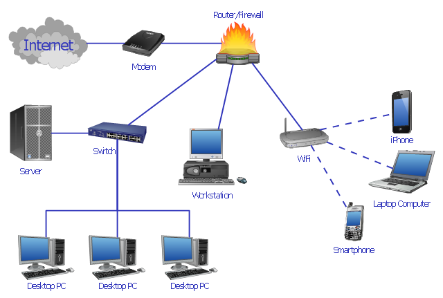
- Modem Router Server Layout
- How To use Switches in Network Diagram | Computer network ...
- Firewall Server Router Switch Cable
- Hotel Network Topology Diagram | Star Network Topology | Wireless ...
- Star Topology With Server Router Modem Firewall And Internet
- Firewall between LAN and WAN | Hotel Network Topology Diagram ...
- Network Glossary Definition | Bus network topology diagram ...
- Switch Firewall Router Connection Diagram
- A Sketch With The Following Devices Modem Nic Switches Router
- Network Diagram Cloud Firewall Workstation Switch Server
- Cisco network topology - Vector stencils library | Computer network ...
- Router Modem Switch Hub
- Star Network Topology | Network Topologies | Fully Connected ...
- Network hardware - Vector stencils library | Bus network topology ...
- How To use Switches in Network Diagram | Star Network Topology ...
- Firewall between LAN and WAN | Network Security Diagrams ...
- Cisco network topology - Vector stencils library | Cisco network ...
- Router Firewall Switch Diagram
- Network Gateway Router | Hotel Network Topology Diagram | Cisco ...
- Network Topologies | Network Printer | Network Gateway Router ...
- ERD | Entity Relationship Diagrams, ERD Software for Mac and Win
- Flowchart | Basic Flowchart Symbols and Meaning
- Flowchart | Flowchart Design - Symbols, Shapes, Stencils and Icons
- Flowchart | Flow Chart Symbols
- Electrical | Electrical Drawing - Wiring and Circuits Schematics
- Flowchart | Common Flowchart Symbols
- Flowchart | Common Flowchart Symbols