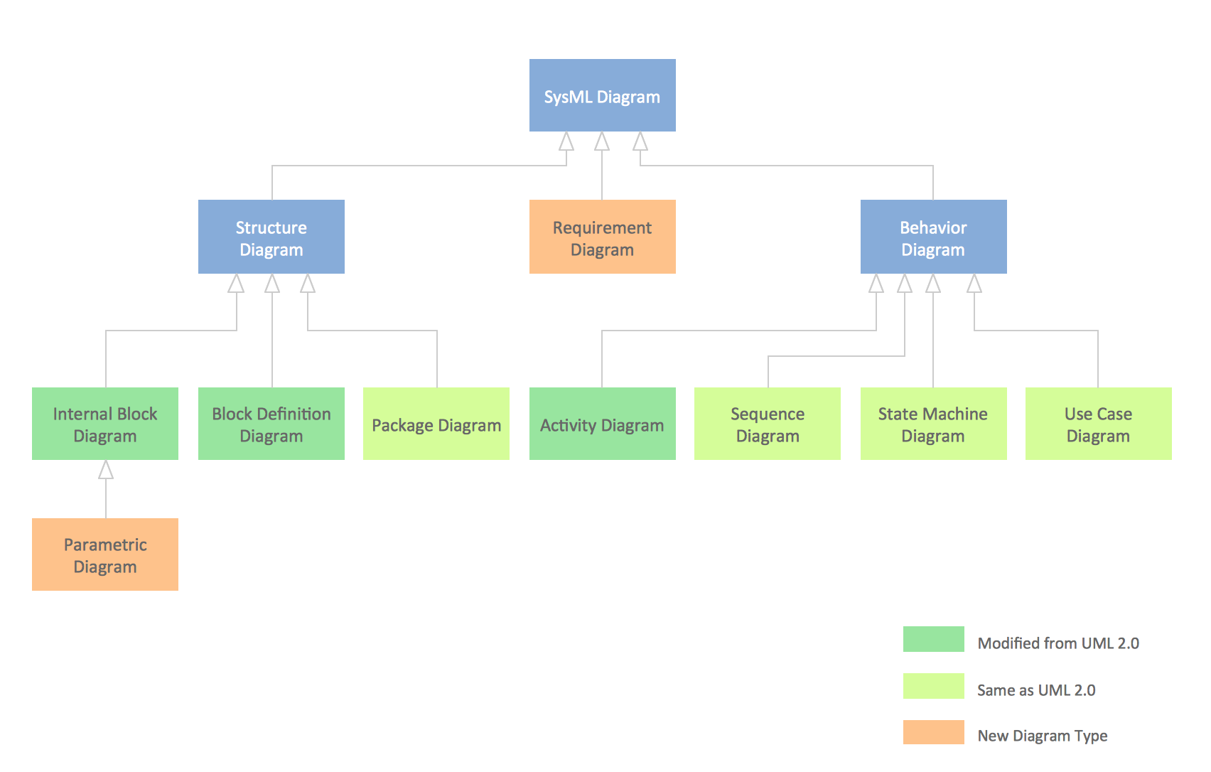
SysML Diagram
ORM Diagram

Software Diagrams

ConceptDraw DIAGRAM is a perfect tool for Designing and planning tasks; Developing Visualization Solutions; Project Planning (Gantt Charts, Timelines, Project Schedules).
Software Diagram Examples and Templates

Software Development area of ConceptDraw Solution Park provides 5 solutions:
Data Flow Diagrams, Entity-Relationship Diagram (ERD), Graphic User Interface, IDEFO Diagrams, Rapid UML.
UML Class Diagram Constructor

The Rapid UML Solution for ConceptDraw DIAGRAM includes the UML Class Diagram library that helps you to design the UML Class Diagram quick and easy. You can simply and quickly drop the ready-to-use objects from the library into your document to create the UML Class Diagram.
About UML

This sample shows the work of the taxi service and is used by taxi stations, by airports, in the tourism field and delivery service.
IDEF4 Standard

This SysML diagram example was redesigned from Wikimedia Commons file: Use case restaurant model.svg.
"Use case model of a restaurant business." [commons.wikimedia.org/ wiki/ File:Use_ case_ restaurant_ model.svg]
"The use case diagram describes the usage of a system (subject) by its actors (environment) to achieve a goal, that is
realized by the subject providing a set of services to selected actors. The use case can also be viewed as functionality and/
or capabilities that are accomplished through the interaction between the subject and its actors. Use case diagrams include the use case and actors and the associated communications between them. Actors represent classifier roles that are external to the system that may correspond to users, systems, and or other environmental entities. They may interact either directly or indirectly with the system. The actors are often specialized to represent a taxonomy of user types or external systems." [omg.org/ spec/ SysML/ 1.3/ ]
The SysML diagram example "Use case restaurant model" was drawn using the ConceptDraw PRO diagramming and vector drawing software extended with the SysML solution from the Software Development area of ConceptDraw Solution Park.
Example of SysML use case diagram

SysML

ConceptDraw DIAGRAM diagramming and vector drawing software was extended with SysML Solution from the Software Development Area of ConceptDraw Solution Park specially to help systems engineers design various model systems with SysML.
How To Create Floor Plans


Biology Drawing
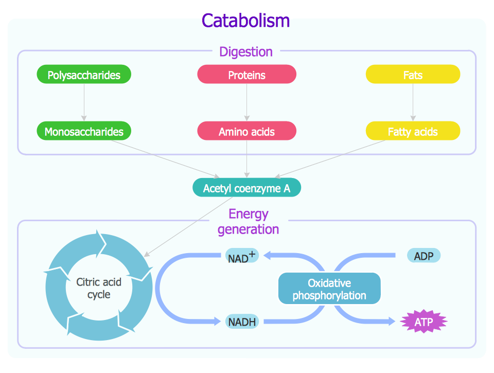
ConceptDraw DIAGRAM diagramming and vector drawing software extended with Biology solution from the Science and Education area offers the useful tools for easy biology drawing.
Chemistry Equation Symbols

Chemistry solution provides the Chemical Drawings Library with large quantity of vector chemistry equation symbols to help you create professional looking chemistry diagrams quick and easy.
- Model Taxonomy Software Diagram
- Express-G Diagram | Software Diagram Examples and Templates ...
- Jacobson Use Cases Diagram | Use case restaurant model | UML ...
- Basic Flowchart Symbols and Meaning | Process Flowchart | Data ...
- Jacobson Use Cases Diagram | Use case restaurant model | SYSML ...
- Business Process Modeling with ConceptDraw | Diagramming ...
- Data Flow Diagram Model | Data Flow Diagram Software | Data Flow ...
- ORM Diagram | Software Diagrams | SSADM Diagram | Freeware To ...
- Telecommunication networks. Computer and Network Examples ...
- SysML | Use case restaurant model | Systems Engineering ...
- Jacobson Use Cases Diagram | Use case restaurant model | UML ...
- ORM Diagram | Software Diagrams | Program Structure Diagram ...
- SysML Diagram | Diagramming Software for Design UML ...
- Jacobson Use Cases Diagram | Use case restaurant model | UML ...
- Jacobson Use Cases Diagram | UML Use Case Diagram Example ...
- Coad Yourdon Model Software Design Wiki
- COM and OLE Diagram | Martin ERD Diagram | Software Diagrams ...
- Jacobson Use Cases Diagram | Use case restaurant model | UML ...
- Memory Object Diagram | Program Structure Diagram | SysML ...
- SysML | Model Based Systems Engineering | Data Modeling ...
- ERD | Entity Relationship Diagrams, ERD Software for Mac and Win
- Flowchart | Basic Flowchart Symbols and Meaning
- Flowchart | Flowchart Design - Symbols, Shapes, Stencils and Icons
- Flowchart | Flow Chart Symbols
- Electrical | Electrical Drawing - Wiring and Circuits Schematics
- Flowchart | Common Flowchart Symbols
- Flowchart | Common Flowchart Symbols