Home Electrical Plan

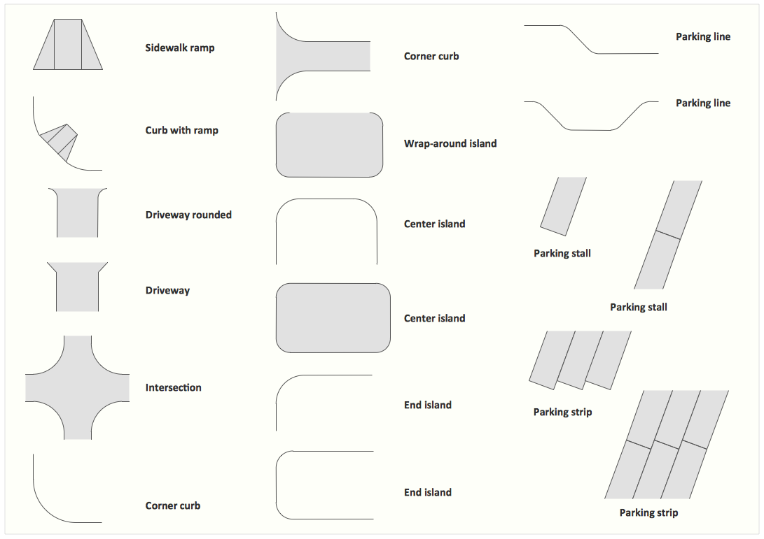
Interior Design. Site Plan — Design Elements
Once you try ConceptDraw DIAGRAM product, you will recommend it to lots of other people you know and you care for, such as your friends, acquaintances, colleagues and business partners as this application is truly incredible and useful in drawing so many things which can be helpful for your use.
Physical Security Plan

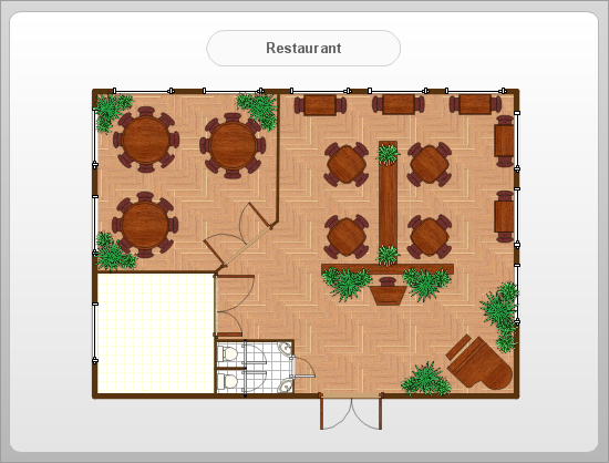
How to Draw a Building Plans
Functional Block Diagram

Fault Tree Analysis Software

First of all, Fault Tree Analysis Diagrams Solution provides a set of samples which are the good examples of easy drawing professional looking Fault Tree Analysis Diagrams.
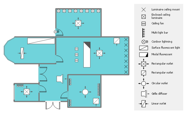
This reflected ceiling plan (RCP) sample shows lighting and HVAC layout.
"A "reflected ceiling plan" shows a view of the room as if looking from above, through the ceiling, at a mirror installed one foot below the ceiling level, which shows the reflected image of the ceiling above. This convention maintains the same orientation of the floor and ceilings plans - looking down from above. Reflected Ceiling Plans or RCP's are used by designers and architects to demonstrate lighting, visible mechanical features, and ceiling forms as part of the documents provided for construction." [Floor plan. Wikipedia]
The lighting and HVAC layout example "Reflected ceiling plan" was created using the ConceptDraw DIAGRAM diagramming and vector drawing software extended with the Reflected Ceiling Plans solution from the Building Plans area of ConceptDraw Solution Park.
Lighting and HVAC layout
- Mechanical Fitting Diagrams
- Mechanical Fitter Diagram
- Welding symbols | Mechanical Engineering | Design elements ...
- Examples Of Fitting Symbols With Diagrams
- Butt weld geometry | Mechanical Engineering | Mechanical Drawing ...
- Mechanical Drawing Symbols | Retract resistor check valve ...
- Interior Design Piping Plan - Design Elements | Mechanical Drawing ...
- How To use House Electrical Plan Software | Electrical Drawing ...
- Mechanical Drawing Symbols | Mechanical Drawing Software ...
- Piping and Instrumentation Diagram Software | Mechanical Drawing ...
- Mechanical Drawing Symbols | Design elements - Valves | Design ...
- Mechanical Drawing Symbols | Design elements - Pipes (part 2 ...
- Welding symbols | Mechanical Drawing Symbols | Design elements ...
- Mechanical Drawing Symbols | Mechanical Engineering | Process ...
- Process Flowchart | Half Pipe Plans | Mechanical Drawing Symbols ...
- Pipe Symbol
- Mechanical Drawing Symbols | Piping and Instrumentation Diagram ...
- Symbols Of Materials Used In Technical Drawing
- Mechanical Drawing Symbols | Mechanical Drawing Software ...
- Mechanical Drawing Symbols | Mechanical Engineering | Circuits ...
- ERD | Entity Relationship Diagrams, ERD Software for Mac and Win
- Flowchart | Basic Flowchart Symbols and Meaning
- Flowchart | Flowchart Design - Symbols, Shapes, Stencils and Icons
- Flowchart | Flow Chart Symbols
- Electrical | Electrical Drawing - Wiring and Circuits Schematics
- Flowchart | Common Flowchart Symbols
- Flowchart | Common Flowchart Symbols