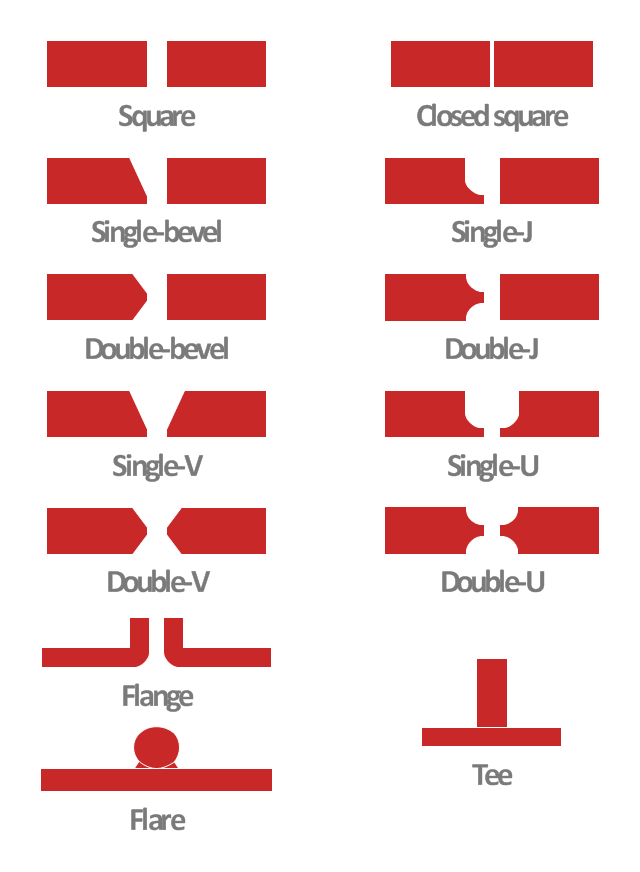
This engineering drawing shows different types of geometry of butt welds.
"Welds can be geometrically prepared in many different ways. The five basic types of weld joints are the butt joint, lap joint, corner joint, edge joint, and T-joint (a variant of this last is the cruciform joint). Other variations exist as well - for example, double-V preparation joints are characterized by the two pieces of material each tapering to a single center point at one-half their height. Single-U and double-U preparation joints are also fairly common - instead of having straight edges like the single-V and double-V preparation joints, they are curved, forming the shape of a U. Lap joints are also commonly more than two pieces thick - depending on the process used and the thickness of the material, many pieces can be welded together in a lap joint geometry." [Welding. Wikipedia]
This engineering drawing example was redesigned using the ConceptDraw PRO diagramming and vector drawing software from the Wikimedia Commons file: Butt Weld Geometry.GIF.
[commons.wikimedia.org/ wiki/ File:Butt_ Weld_ Geometry.GIF]
The engineering drawing example "Butt weld geometry" is included in the Mechanical Engineering solution from the Engineering area of ConceptDraw Solution Park.
Network Diagram Software
ConceptDraw DIAGRAM is the best network diagram software that allows to draw Logical Network Diagram, Network Communication Plan, Network Floor Plan Layout, Active Directory Diagram, Cisco Network Diagram, LAN and WAN Diagram.Our network drawing software has numerous network design diagram examples and templates:
GPRS Network Scheme,
GPS Operation Diagram,
Hybrid Network Diagram,
Mobile Satellite Communication Network,
Mobile TV Network Diagram,
Web-based Network Diagram,
Wireless Broadband Network Diagram,
Wireless Router Network Diagram.
You can use the more than 2 000 pre-designed stencils for making custom network diagrams.

HelpDesk
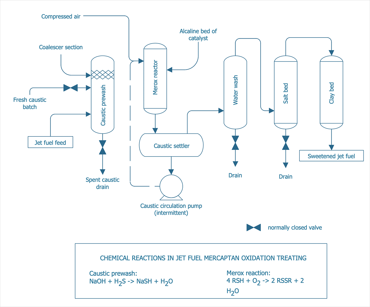
How to Draw a Chemical Process Flow Diagram
Process Flow Diagram widely used in modeling of processes in the chemical industry. A Chemical Process Flow diagram (PFD) is a specialized type of flowchart. With the help of Chemical Process Flow Diagram, engineers can easily specify the general scheme of the processes and chemical plant equipment. Chemical Process Flow Diagram displays the real scheme of the chemical process, the relationship between the equipment and the technical characteristics of the process. Chemical Process Flow Diagram illustrates the connections between the basic equipment as well as the overall structure of pipelines and other supporting equipment. The purpose of the PFD is to build the image of the basic idea of the chemical process. ConceptDraw DIAGRAM together with its Chemical and Process Engineering solution delivers the possibility to design Chemical Process Flow diagrams. It is designed for chemical industry engineers and designers.- Mechanical Engineering Diagram Gif
- Mechanical Engineering | Mechanical Drawing Symbols ...
- Electrical Wiring Diagram Software Gif
- Hydraulic schematic | Bank ATM use case diagram | Basic Flowchart ...
- A Diagram Of AT Joint
- Butt weld geometry | Butt weld geometry | Mechanical Engineering ...
- How To Create CCTV Network Diagram | Rotation Gif
- Circuit diagram - EL 34 schematics | International Gif
- Diagram Of T Joint Welding
- Butt weld geometry | Mechanical Engineering | Mechanical Drawing ...
- Butt weld geometry | Mechanical Engineering | Diagram Of Five ...
- Types Of Welding With Diagram
- Butt weld geometry | Mechanical Engineering | Diagram For Various ...
- Welded joints types | Mechanical Engineering | Butt weld geometry ...
- Diagrams Of Welded Joint Joints
- Butt weld geometry | Mechanical Engineering | Show The Diagram ...
- Butt weld geometry | Mechanical Engineering | Mechanical Drawing ...
- Butt weld geometry | Mechanical Engineering | Interior Design ...
- Butt weld geometry | Mechanical Engineering | Welding symbols ...
- Butt weld geometry | Mechanical Engineering | Design elements ...
- ERD | Entity Relationship Diagrams, ERD Software for Mac and Win
- Flowchart | Basic Flowchart Symbols and Meaning
- Flowchart | Flowchart Design - Symbols, Shapes, Stencils and Icons
- Flowchart | Flow Chart Symbols
- Electrical | Electrical Drawing - Wiring and Circuits Schematics
- Flowchart | Common Flowchart Symbols
- Flowchart | Common Flowchart Symbols


