"The symbols and conventions used in welding documentation are specified in national and international standards such as ISO 2553 Welded, brazed and soldered joints -- Symbolic representation on drawings and ISO 4063 Welding and allied processes -- Nomenclature of processes and reference numbers. The US standard symbols are outlined by the American National Standards Institute and the American Welding Society and are noted as "ANSI/ AWS".
In engineering drawings, each weld is conventionally identified by an arrow which points to the joint to be welded. The arrow is annotated with letters, numbers and symbols which indicate the exact specification of the weld. In complex applications, such as those involving alloys other than mild steel, more information may be called for than can comfortably be indicated using the symbols alone. Annotations are used in these cases." [Symbols and conventions used in welding documentation. Wikipedia]
The example chart "Elements of welding symbol" is redesigned using the ConceptDraw PRO diagramming and vector drawing software from the Wikipedia file: Elements of a welding symbol.PNG.
[en.wikipedia.org/ wiki/ File:Elements_ of_ a_ welding_ symbol.PNG]
The diagram example "Elements location of a welding symbol" is contained in the Mechanical Engineering solution from the Engineering area of ConceptDraw Solution Park.
Welding joint symbol chart

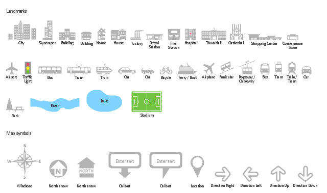
The vector stencils library "Landmarks" contains 34 signs and pictograms for drawing road and transit maps.
The vector stencils library "Map symbols" contains 10 signs and pictograms for drawing road and transit maps.
"A landmark is a recognizable natural or man-made feature used for navigation, a feature that stands out from its near environment and is often visible from long distances.
In modern use, the term can also be applied to smaller structures or features, that have become local or national symbols." [Landmark. Wikipedia]
The pictograms example "Design elements - Location map" was created using the ConceptDraw PRO diagramming and vector drawing software extended with the Spatial Infographics solution from the Maps area of ConceptDraw Solution Park.
Landmarks and Map symbols
Using Remote Networking Diagrams


How To use House Electrical Plan Software

You can use many of built-in templates, electrical symbols and electical schemes examples of our House Electrical Diagram Software.
ConceptDraw is a fast way to draw: Electrical circuit diagrams, Schematics, Electrical Wiring, Circuit schematics, Digital circuits, Wiring in buildings, Electrical equipment, House electrical plans, Home cinema, Satellite television, Cable television, Closed-circuit television.
House Electrical Plan Software works across any platform, meaning you never have to worry about compatibility again. ConceptDraw PRO allows you to make electrical circuit diagrams on PC or macOS operating systems.

The vector stencils library "Map symbols" contains 10 spatial infographics symbols.
Use these signs and pictograms for drawing road and transit maps in the ConceptDraw PRO diagramming and vector drawing software extended with the Spatial Infographics solution from the area "What is Infographics" of ConceptDraw Solution Park.
Use these signs and pictograms for drawing road and transit maps in the ConceptDraw PRO diagramming and vector drawing software extended with the Spatial Infographics solution from the area "What is Infographics" of ConceptDraw Solution Park.
Windrose

North arrow
North arrow
Callout

Callout

Location

Direction Right

Direction Left

Direction Up

Direction Down

The vector stencils library "Cable TV" contains 64 symbols of cable TV network equipment.
Use these shapes for drawing CATV system design floor plans, network topology diagrams, wiring diagrams and cabling layout schemes in the ConceptDraw PRO diagramming and vector drawing software.
The vector stencils library "Cable TV" is included in the Electric and Telecom Plans solution from the Building Plans area of ConceptDraw Solution Park.
Output Directional Tap 1

Output Directional Tap 2

Output Directional Tap 3

Output Directional Tap 4

Output Directional Tap 5

2-way Splitter

3-way Splitter

4-way Splitter

AC Power Block

Bond

Down Guy

Building Guy and Anchor

Rock Guy with Anchor

Down Guy with Anchor

Pole-to-Pole Guy

Sidewalk Down Guy with Anchor

Sidewalk Down Guy

Slack Span Messenger Wire

Tensioned Messenger Wire w/out cable

Tensioned Messenger Wire

Ground

Joint Usage (Power & Telephone Pole)
-cable-tv---vector-stencils-library.png--diagram-flowchart-example.png)
Joint Usgae Pole with Transformer

Strut

Tree Guy with Anchor

Push Brace (smaller pole in actual relative position)
-cable-tv---vector-stencils-library.png--diagram-flowchart-example.png)
Extension Arm

Built CATV Pole

Proposed CATV Pole

Directional Tap 1

Directional Tap 2

Manhole

Telephone Pole

Riser Pole

Vault Handheld

Fixed Equalizer

Fixed Flat Attenuators

Other Supporting Structures

Pedestal - Underground Routing

Power Pole

Direct Buried Underground Routing

Duct Line Underground Routing

Line Terminations

2-Way Optical Splice Location

3-Way Optical Splice Location

4-Way Optical Splice Location

> 4-Way Optical Splice Location

Optical Amplifier

Cable AC Power Combiner

Optical Fiber Cable

Optical Connector

Wavelength Demultiplexer

Wavelength Multiplexer

Optical Transmitter

Optical Transmitter

Optical Node

Optical Splitter

Headend (Signal Processing)
-cable-tv---vector-stencils-library.png--diagram-flowchart-example.png)
Node

Primary Hub

Secondary Hub

Coaxial Splice

Power Supply

Variable Equalizer

The vector stencils library "Qualifying" contains 56 qualifying symbols of radiation, polarity, phase, windings, wire, ground, connection, connector, coaxial, electret.
Use these signs to annotate or specify characteristics of objects in electrical drawings, electronic schematics, circuit diagrams, electromechanical drawings, and wiring diagrams, cabling layout diagrams.
"An electrical drawing, is a type of technical drawing that shows information about power, lighting, and communication for an engineering or architectural project. Any electrical working drawing consists of "lines, symbols, dimensions, and notations to accurately convey an engineering's design to the workers, who install the electrical system on the job".
A complete set of working drawings for the average electrical system in large projects usually consists of:
(1) A plot plan showing the building's location and outside electrical wiring.
(2) Floor plans showing the location of electrical systems on every floor.
(3) Power-riser diagrams showing panel boards.
(4) Control wiring diagrams.
(5) Schedules and other information in combination with construction drawings.
Electrical drafters prepare wiring and layout diagrams used by workers who erect, install, and repair electrical equipment and wiring in communication centers, power plants, electrical distribution systems, and buildings." [Electrical drawing. Wikipedia]
The signs example "Design elements - Qualifying" was drawn using the ConceptDraw PRO diagramming and vector drawing software extended with the Electrical Engineering solution from the Engineering area of ConceptDraw Solution Park.
Qualifying symbols

Design Data Flow. DFD Library

Basic Flowchart Symbols and Meaning


Cisco Products Additional. Cisco icons, shapes, stencils and symbols
")
Business Process Flowchart Symbols

HelpDesk
How to Create a New Library

Thus, the new library and its objects will be indexed to be searched and used in the further diagrams.
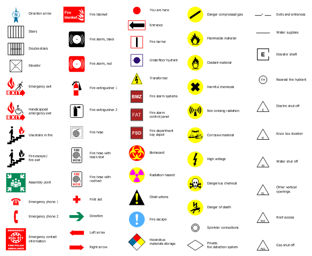
The design elements library "Fire and emergency planning" contains 58 fire safety symbols for developing the fire escape plans using the ConceptDraw PRO diagramming and vector drawing software.
The fire escape plan shows the location of fire alarm and extinguishing equipment, stairs and emergency exits, and evacuation orders and path.
"Hazard symbols are recognizable symbols designed to warn about hazardous materials, locations, or objects, including electric currents, poisons, and other things. The use of hazard symbols is often regulated by law and directed by standards organizations. Hazard symbols may appear with different colors, backgrounds, borders and supplemental information in order to specify the type of hazard." [Hazard symbol. Wikipedia]
The vector stencils library Fire and emergency planning is included in the Fire and Emergency Plans solution from the Building Plans" area of ConceptDraw Solution Park.
Safety symbols
HelpDesk
How to Create a Residential Plumbing Plan

Office Layout

You can use many of built-in templates and examples of our Office Layout Software. Start with the exact template you need then customize to fit your needs with more than 10000 stencils and you will find expected result in minutes.

HelpDesk
How to Create a Directional Map Using ConceptDraw PRO

HelpDesk
How to Save a Drawing as a Graphic File

This cafe electrical floor plan sample shows the outlet and switch layout.
"An electrical drawing, is a type of technical drawing that shows information about power, lighting, and communication for an engineering or architectural project. Any electrical working drawing consists of "lines, symbols, dimensions, and notations to accurately convey an engineering's design to the workers, who install the electrical system on the job".
A complete set of working drawings for the average electrical system in large projects usually consists of:
(1) A plot plan showing the building's location and outside electrical wiring.
(2) Floor plans showing the location of electrical systems on every floor.
(3) Power-riser diagrams showing panel boards.
(4) Control wiring diagrams.
(5) Schedules and other information in combination with construction drawings.
Electrical drafters prepare wiring and layout diagrams used by workers who erect, install, and repair electrical equipment and wiring in communication centers, power plants, electrical distribution systems, and buildings." [Electrical drawing. Wikipedia]
The outlet and switch layout example "Cafe electrical floor plan" was created using the ConceptDraw PRO diagramming and vector drawing software extended with the Electric and Telecom Plans solution from the Building Plans area of ConceptDraw Solution Park.
Outlet and switch layout

The Data flow diagram (DFD) example "Payment for goods using UPS code scanner" shows data flow in process of payment for goods in the shop using the MaxiCode scanner.
"MaxiCode is a public domain, machine-readable symbol system originally created and used by United Parcel Service. Suitable for tracking and managing the shipment of packages, it resembles a barcode, but uses dots arranged in a hexagonal grid instead of bars. MaxiCode has been standardised under ISO/ IEC 16023.
A MaxiCode symbol (internally called "Bird's Eye", "Target", "dense code", or "UPS code") appears as a 1 inch square, with a bullseye in the middle, surrounded by a pattern of hexagonal dots. It can store about 93 characters of information, and up to 8 MaxiCode symbols can be chained together to convey more data. The centered symmetrical bullseye is useful in automatic symbol location regardless of orientation, and it allows MaxiCode symbols to be scanned even on a package traveling rapidly." [MaxiCode. Wikipedia]
This example of data flow diagram (Gane & Sarson notation) was created using the ConceptDraw PRO diagramming and vector drawing software extended with the Data Flow Diagrams solution from the Software Development area of ConceptDraw Solution Park.
DFD
---payment-for-goods-using-ups-code-scanner.png--diagram-flowchart-example.png)
- Mechanical Drawing Symbols | Mechanical Engineering | Elements ...
- Mechanical Drawing Symbols | Elements location of a welding ...
- Elements location of a welding symbol | Basic Nomenclature In ...
- Mechanical Engineering Drawing Symbols Chart
- Elements location of a welding symbol | Engineering Drawing ...
- Elements location of a welding symbol | Mechanical Engineering ...
- Elements location of a welding symbol | Welding symbols | Design ...
- Mechanical Drawing Symbols | Welding symbols | Elements location ...
- Elements location of a welding symbol | Welding symbols ...
- Technical Drawing Software | Elements location of a welding symbol ...
- Elements location of a welding symbol | Elements location of a ...
- Welding symbols | Elements location of a welding symbol | Design ...
- Butt weld geometry | Welding symbols | Elements location of a ...
- Elements location of a welding symbol | Welding symbols | Design ...
- Mechanical Engineering | Elements location of a welding symbol ...
- Elements location of a welding symbol | Iso Welding Symbols
- Elements location of a welding symbol | Design elements - Welding ...
- Welding symbols | Elements location of a welding symbol | Welded ...
- Welded joints types | Butt weld geometry | Elements location of a ...
- Types of Welding in Flowchart | Elements location of a welding ...
- ERD | Entity Relationship Diagrams, ERD Software for Mac and Win
- Flowchart | Basic Flowchart Symbols and Meaning
- Flowchart | Flowchart Design - Symbols, Shapes, Stencils and Icons
- Flowchart | Flow Chart Symbols
- Electrical | Electrical Drawing - Wiring and Circuits Schematics
- Flowchart | Common Flowchart Symbols
- Flowchart | Common Flowchart Symbols