How To use House Electrical Plan Software

You can use many of built-in templates, electrical symbols and electical schemes examples of our House Electrical Diagram Software.
ConceptDraw is a fast way to draw: Electrical circuit diagrams, Schematics, Electrical Wiring, Circuit schematics, Digital circuits, Wiring in buildings, Electrical equipment, House electrical plans, Home cinema, Satellite television, Cable television, Closed-circuit television.
House Electrical Plan Software works across any platform, meaning you never have to worry about compatibility again. ConceptDraw DIAGRAM allows you to make electrical circuit diagrams on PC or macOS operating systems.

Electrical Symbols, Electrical Diagram Symbols

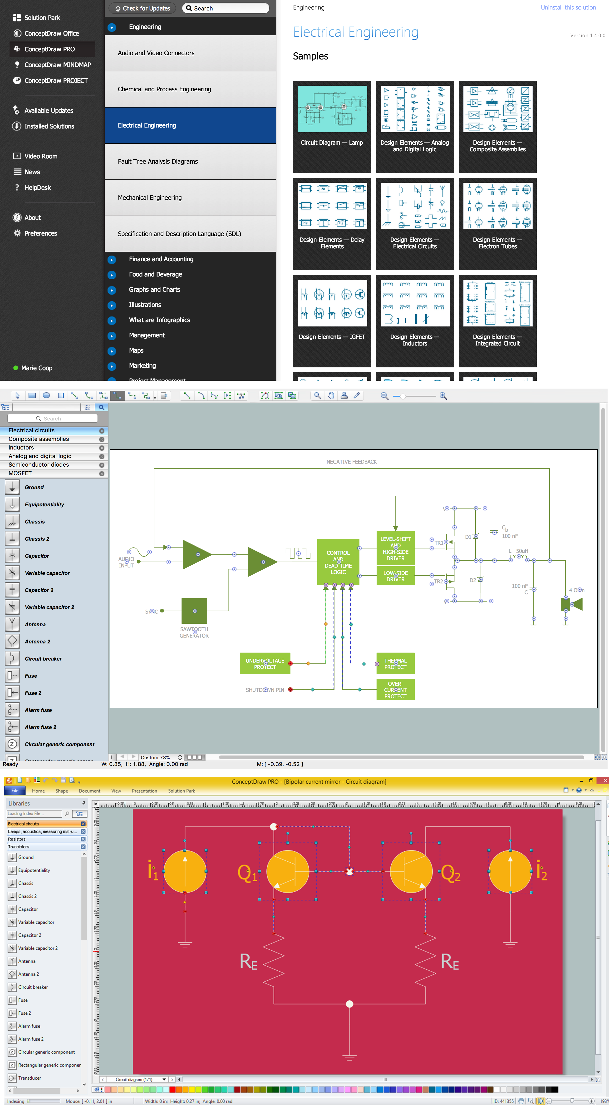
This solution provides 26 libraries which contain 926 electrical symbols from electrical engineering: Analog and Digital Logic, Composite Assemblies, Delay Elements, Electrical Circuits, Electron Tubes, IGFET, Inductors, Integrated Circuit, Lamps, Acoustics, Readouts, Logic Gate Diagram, MOSFET, Maintenance, Power Sources, Qualifying, Resistors, Rotating Equipment, Semiconductor Diodes, Semiconductors, Stations, Switches and Relays, Terminals and Connectors, Thermo, Transformers and Windings, Transistors, Transmission Paths,VHF UHF SHF.
The vector stencils library "Electrical and telecom" contains 83 symbols of electrical and telecommunication equipment for electrical drawings and wiring diagrams of buildings, communication centers, power plants and electrical distribution systems.
"An electrical drawing, is a type of technical drawing that shows information about power, lighting, and communication for an engineering or architectural project." [Electrical drawing. Wikipedia]
Use the design elements library "Electrical and telecom" to design your own electrical drawings, plot plans of the building outside electrical wiring, floor plans with electrical and telecommunication systems layout, power-riser diagrams with panel boards, control wiring diagrams and cabling layout schemes, reflected ceiling plans and lighting panels layouts using the ConceptDraw PRO diagramming and vector drawing software.
The shapes library "Electrical and telecom" is included in the Electric and Telecom Plans solution from the Building Plans area of ConceptDraw Solution Park.
Electrical and telecom symbols

Home Electrical Plan

Electrical Symbols — Terminals and Connectors

26 libraries of the Electrical Engineering Solution of ConceptDraw DIAGRAM make your electrical diagramming simple, efficient, and effective. You can simply and quickly drop the ready-to-use objects from libraries into your document to create the electrical diagram.
Wiring Diagrams with ConceptDraw DIAGRAM
The vector stencils library "Qualifying" contains 56 qualifying symbols of radiation, polarity, phase, windings, wire, ground, connection, connector, coaxial, electret.
Use these signs to annotate or specify characteristics of objects in electrical drawings, electronic schematics, circuit diagrams, electromechanical drawings, and wiring diagrams, cabling layout diagrams.
"An electrical drawing, is a type of technical drawing that shows information about power, lighting, and communication for an engineering or architectural project. Any electrical working drawing consists of "lines, symbols, dimensions, and notations to accurately convey an engineering's design to the workers, who install the electrical system on the job".
A complete set of working drawings for the average electrical system in large projects usually consists of:
(1) A plot plan showing the building's location and outside electrical wiring.
(2) Floor plans showing the location of electrical systems on every floor.
(3) Power-riser diagrams showing panel boards.
(4) Control wiring diagrams.
(5) Schedules and other information in combination with construction drawings.
Electrical drafters prepare wiring and layout diagrams used by workers who erect, install, and repair electrical equipment and wiring in communication centers, power plants, electrical distribution systems, and buildings." [Electrical drawing. Wikipedia]
The signs example "Design elements - Qualifying" was drawn using the ConceptDraw PRO diagramming and vector drawing software extended with the Electrical Engineering solution from the Engineering area of ConceptDraw Solution Park.
Qualifying symbols

Electrical Symbols, Electrical Schematic Symbols

Electrical Drawing Software and Electrical Symbols

Electrical Drawing Software provides the 26 stencils libraries of ready-to-use predesigned vector electrical symbols, templates and samples that make your electrical drawing quick, easy and effective.
How To Create Restaurant Floor Plan in Minutes
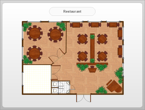
It helps make a layout for a restaurant — restaurant floor plans, cafe floor plans, bar area, floor plan of a fast food restaurant, restaurant furniture layout, etc.
ConceptDraw DIAGRAM — great restaurant floor planner. You do not need to be an artist to create great-looking restaurant floor plans in minutes.

- Lighting Panel Board Symbol
- Power Panel Board Symbol
- Symbol Of Power Distribution Board
- Symbol Use For Panel Board For Lighting
- Power Distribution Board Symbol
- Cafe electrical floor plan | Electrical Symbol Of Main Fuse Board ...
- Lighting Panel Symbol
- Panal Board Scheme Symbol
- Wiring Diagrams with ConceptDraw PRO | Main Fuse Board Symbol
- Panelboard For Office Diagram
- ERD | Entity Relationship Diagrams, ERD Software for Mac and Win
- Flowchart | Basic Flowchart Symbols and Meaning
- Flowchart | Flowchart Design - Symbols, Shapes, Stencils and Icons
- Flowchart | Flow Chart Symbols
- Electrical | Electrical Drawing - Wiring and Circuits Schematics
- Flowchart | Common Flowchart Symbols
- Flowchart | Common Flowchart Symbols