Entity Relationship Diagram Software Engineering

Professional ERD drawing is an essential software engineering method for database modeling. ConceptDraw DIAGRAM as a powerful Entity Relationship Diagram Software Engineering offers the tools of Entity-Relationship Diagram (ERD) solution from Software Development area of ConceptDraw Solution Park.
Entity Relationship Diagram Symbols

ERD symbols used for professional ERD drawing are collected in libraries from the Entity-Relationship Diagram (ERD) solution for ConceptDraw DIAGRAM.
Data structure diagram with ConceptDraw DIAGRAM

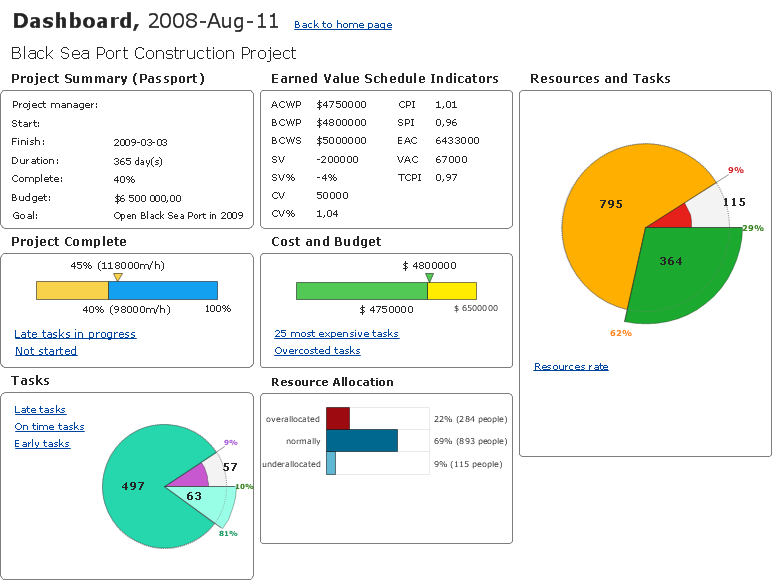
How To Create Project Report
JSD - Jackson system development

When implementing the Jackson System Development method and designing JSD diagrams, you can succesfully use the powerful and helpful tools of ConceptDraw DIAGRAM software extended with Entity-Relationship Diagram (ERD) solution from the Software Development area of ConceptDraw Solution Park.
Yourdon and Coad Diagram

Data Modeling Diagram

COM and OLE Diagram

Data Flow Diagram Examples

Software and Database Design with ConceptDraw DIAGRAM

UML diagramming; designing and prototyping Graphical User Interface (GUI); flowcharts, data flow diagrams; database and ERD diagramming (Chen ERD, Database Model diagram, Express-G, Martin ERD, ORM Diagrams and more); SSADM diagrams, Booch diagrams, Nassi-Shneiderman diagrams with special flowchart symbols.
- ER Diagram Of E Learning System
- Entity-Relationship Diagram ( ERD ) | Entity-Relationship Diagram ...
- Entity-Relationship Diagram ( ERD ) | Example of DFD for Online ...
- eLearning for Skype | Entity-Relationship Diagram ( ERD ) | Fishbone ...
- Entity-Relationship Diagram ( ERD ) | Entity-Relationship Diagram ...
- Entity Relationship Diagram For Learning Management System
- Learn Er Diagram Relationships
- UML Class Diagram Notation | Design elements - ERD (crow's foot ...
- Entity Relationship Diagram For E Learning System
- Chen Notation | Design elements - ER diagram (Chen notation ...
- ERD | Entity Relationship Diagrams, ERD Software for Mac and Win
- Flowchart | Basic Flowchart Symbols and Meaning
- Flowchart | Flowchart Design - Symbols, Shapes, Stencils and Icons
- Flowchart | Flow Chart Symbols
- Electrical | Electrical Drawing - Wiring and Circuits Schematics
- Flowchart | Common Flowchart Symbols
- Flowchart | Common Flowchart Symbols