The vector stencils library "Network layout floorplan" contain 34 symbol icons for drawing computer network floor plans and communication equipment and cabling layouts.
"Networking hardware may also be known as network equipment or computer networking devices. Units which are the last receiver or generate data are called hosts or data terminal equipment.
All these terms refer to devices facilitating the use of a computer network. Specifically, they mediate data in a computer network. ...
Typically, networking hardware includes gateways, routers, network bridges, switches, hubs, and repeaters. But it also includes hybrid network devices such as multilayer switches, protocol converters, bridge routers, proxy servers, firewalls, network address translators, multiplexers, network interface controllers, wireless network interface controllers, modems, ISDN terminal adapters, line drivers, wireless access points, networking cables and other related hardware.
The most common kind of networking hardware today is a copper-based Ethernet adapter because of its standard inclusion on most modern computer systems. Wireless networking has, however, become increasingly popular, especially for portable and handheld devices.
Other hardware prevalent in computer networking includes data center equipment (such as file servers, database servers and storage areas), network services (such as DNS, DHCP, email, etc.) as well as devices which assure content delivery." [Networking hardware. Wikipedia]
The shapes example "Design elements - Network layout floorplan" was created using the ConceptDraw PRO diagramming and vector drawing software extended with the Network Layout Floor Plans solution from the Computer and Networks area of ConceptDraw Solution Park.
Network layout floor plan symbols

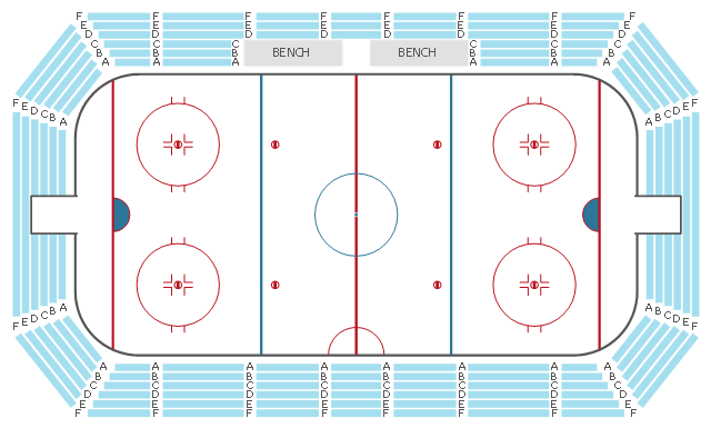
This seating plan sample shows the stadium seat layout.
"A modern stadium (plural stadiums/ stadia) is a place or venue for (mostly) outdoor sports, concerts, or other events and consists of a field or stage either partly or completely surrounded by a structure designed to allow spectators to stand or sit and view the event. ...
Spectator areas and seating.
An "all-seater" stadium has seats for all spectators. Other stadiums are designed so that all or some spectators stand to view the event. The term "all-seater" is not common in the U.S., perhaps because very few American stadiums have sizeable standing-only sections. ...
The spectator areas of a stadium may be referred to as bleachers, especially in the U.S., or as terraces, especially in the United Kingdom, but also in some American baseball parks, as an alternative to the term tier. Originally set out for standing room only, they are now usually equipped with seating. Either way, the term originates from the step-like rows which resemble agricultural terraces. Related, but not precisely the same, is the use of the word terrace to describe a sloping portion of the outfield in a baseball park, possibly, but not necessarily for seating, but for practical or decorative purposes. ... Many stadiums make luxury suites or boxes available to patrons at high prices. These suites can accommodate fewer than 10 spectators or upwards of 30 depending on the venue. Luxury suites at events such as the Super Bowl can cost hundreds of thousands of dollars." [Stadium. Wikipedia]
The seat layout example "Stadium seating plan" was created using the ConceptDraw PRO diagramming and vector drawing software extended with the Seating Plans solution from the Building Plans area of ConceptDraw Solution Park.
Seat layout
- Office Layout Plans | Office Layout | Building Drawing Software for ...
- Two Requirements And Equipment And Layouts Of Modern Drawing
- Requirements And Equipments For Layouts Of Modern Drawing
- Requirements For And Layouts Of Modern Drawing Offices
- Layouts Of Modern Drawing Offices
- Building Drawing Software for Design Office Layout Plan | Modern ...
- Requirments And Equipment For And Layouts Of Modern Drawing
- Requirements And Equipment For And Layout Of Modern Drawing
- Building Drawing Software for Design Office Layout Plan | Office ...
- Building Drawing Software for Design Office Layout Plan | Computer ...
- Building Drawing Software for Design Office Layout Plan | Building ...
- Layouts Of An Modern Drawing
- Building Drawing Software for Design Office Layout Plan | Modern ...
- Building Drawing Software for Design Office Layout Plan | Computer ...
- Building Drawing Software for Design Office Layout Plan | Office ...
- Equipment Of A Layout Of Modern Drawing Office
- Building Drawing Software for Design Office Layout Plan | Hotel ...
- Building Drawing Software for Design Office Layout Plan | Computer ...
- Requirements And Equipments For And Layouts Of The Modern ...
- Building Drawing Software for Design Office Layout Plan | How To ...
- ERD | Entity Relationship Diagrams, ERD Software for Mac and Win
- Flowchart | Basic Flowchart Symbols and Meaning
- Flowchart | Flowchart Design - Symbols, Shapes, Stencils and Icons
- Flowchart | Flow Chart Symbols
- Electrical | Electrical Drawing - Wiring and Circuits Schematics
- Flowchart | Common Flowchart Symbols
- Flowchart | Common Flowchart Symbols