Bubble diagrams in Landscape Design with ConceptDraw PRO
Creation of a bubble diagrams in ConceptDraw is an easy task as you can use the ready scanned location plan instead of plotting paper and paper location plan. Besides scanning of the ready paper location plan you can easy create it using special ConceptDraw libraries and templates for creation room plans and location plans.How To Create Restaurant Floor Plan in Minutes
Restaurant Floor Plans solution for ConceptDraw PRO has 49 extensive restaurant symbol libraries that contains 1495 objects of building plan elements; many examples and templates for drawing floor plans and restaurant layouts.It helps make a layout for a restaurant — restaurant floor plans, cafe floor plans, bar area, floor plan of a fast food restaurant, restaurant furniture layout, etc.
ConceptDraw PRO — great restaurant floor planner. You do not need to be an artist to create great-looking restaurant floor plans in minutes.

How To use House Electrical Plan Software
House Electrical Plan Software for creating great-looking home floor, electrical plan using professional electrical symbols.You can use many of built-in templates, electrical symbols and electical schemes examples of our House Electrical Diagram Software.
ConceptDraw is a fast way to draw: Electrical circuit diagrams, Schematics, Electrical Wiring, Circuit schematics, Digital circuits, Wiring in buildings, Electrical equipment, House electrical plans, Home cinema, Satellite television, Cable television, Closed-circuit television.
House Electrical Plan Software works across any platform, meaning you never have to worry about compatibility again. ConceptDraw PRO allows you to make electrical circuit diagrams on PC or macOS operating systems.

 ConceptDraw Solution Park
ConceptDraw Solution Park collects graphic extensions, examples and learning materials
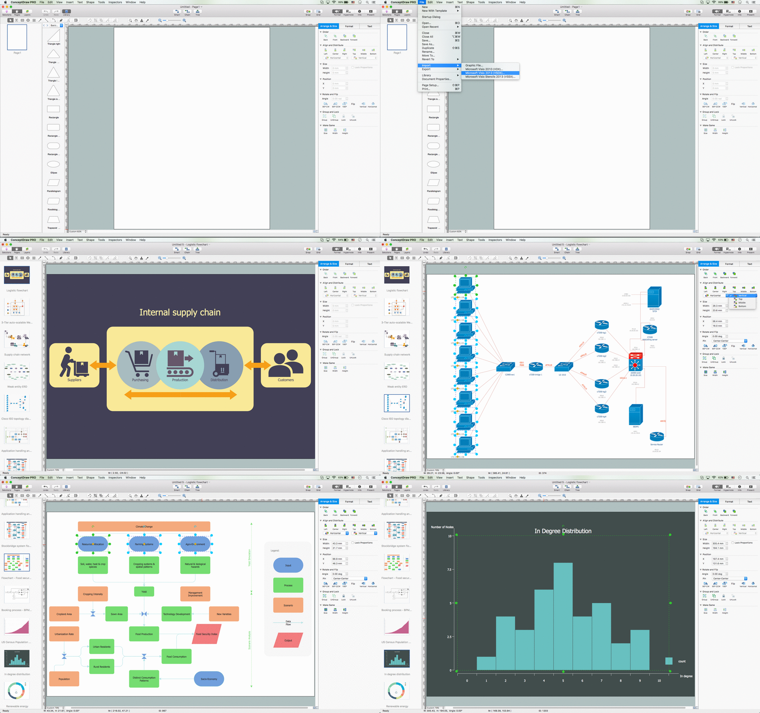
ConceptDraw PRO Compatibility with MS Visio
For those who are migrating from MS Visio to ConceptDraw PRO, or for those who have colleagues and clients who use Visio, ConceptDraw PRO is compatible with MS Visio .VSDX formatted files..VSDX is Visio’s open XML file format, and it can be easily imported and exported by ConceptDraw PRO.Database Flowchart Symbols
Data base diagrams describes inter-related data and tables. It describes roles and relationships, internal and external dependencies, data exchange conventions and structures of knowledge domain.ConceptDraw Software provides number of data-base chart libraries including major 49 vector symbols. Use these DFD flowchart symbol libraries to design data-base structure and models, use it to design data base process-oriented models, or simple data-oriented models. The are special drawing tools for making data flowcharts, data process diagrams, structured analysis diagrams, and information flow diagrams.
 Software Development Area
Solutions from the Software Development Area of ConceptDraw Solution Park collect templates, samples and libraries of vector stencils for drawing the software engineering diagrams and user interface design prototypes.
Information Architecture
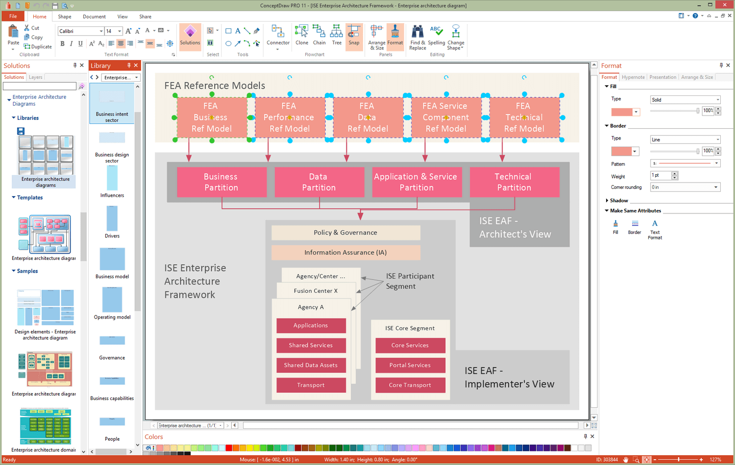
You want design the Information Architecture and need a powerful software for this? ConceptDraw PRO extended with Enterprise Architecture Diagrams Solution from the Management Area is exactly what you need.HelpDesk
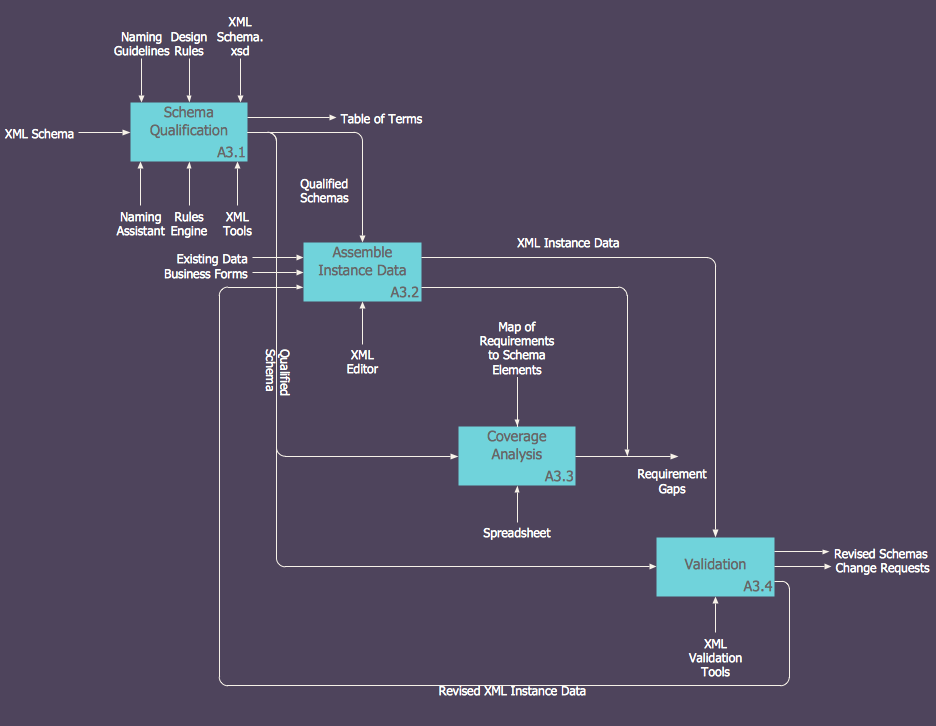
How to Create an IDEF0 Diagram for an Application Development
IDEF0 methods are intended to model the functions of a process, creating a graphical model that displays: what controls the function, who makes it, what resources are used and how they are connected with other functions. The IDEF0 tool is used to model the decisions, actions, and activities of a software system during the development process . IDEF0 diagram graphically depicts a model of a desired version of the application. ConceptDraw PRO allows you to create and communicate the IDEF0 diagrams of any complexity.
 Software Development
This solution extends ConceptDraw PRO v9.4 and helps to accelerate and simplify software development and design by allowing you to draw UML diagrams and prototype Windows and Mac OS user interfaces.
Process Flow Diagram
A Process Flow Diagram (PFD) is a diagram which shows the relationships between the main components in a system. Process Flow Diagrams are widely used by engineers in chemical and process engineering, they allows to indicate the general flow of plant process streams and equipment, helps to design the petroleum refineries, petrochemical and chemical plants, natural gas processing plants, and many other industrial facilities.ConceptDraw PRO diagramming and vector drawing software extended with powerful tools of Flowcharts Solution from the "Diagrams" Area of ConceptDraw Solution Park is effective for drawing: Process Flow Diagram, Flow Process Diagram, Business Process Flow Diagrams.
 Entity-Relationship Diagram (ERD)
An Entity-Relationship Diagram (ERD) is a visual presentation of entities and relationships. That type of diagrams is often used in the semi-structured or unstructured data in databases and information systems. At first glance ERD is similar to a flowch
- How To use Landscape Design Software | ConceptDraw PRO: Able ...
- Bubble diagrams in Landscape Design with ConceptDraw PRO ...
- Landscape Design Icons
- Bubble diagrams in Landscape Design with ConceptDraw PRO ...
- How To use Landscape Design Software | Artwork | How to Design a ...
- Store Layout Software | How To use Landscape Design Software ...
- Store Layout Software | How To use Landscape Design Software ...
- Restaurant Floor Plan Software | Cafe Interior Design | Bubble ...
- Bubble diagrams in Landscape Design with ConceptDraw PRO ...
- Bubble Diagrams | Bubble diagrams in Landscape Design with ...
- Bubble diagrams in Landscape Design with ConceptDraw PRO ...
- Download New Drawing Software For Pc
- Landscape Architecture with ConceptDraw PRO | Building Drawing ...
- Landscape Architecture with ConceptDraw PRO | How To Create ...
- How To Draw Building Plans | How To use House Electrical Plan ...
- Bubble diagrams in Landscape Design with ConceptDraw PRO ...
- Landscape Architecture with ConceptDraw PRO | How to Design a ...
- Bubble diagrams in Landscape Design with ConceptDraw PRO ...
- Bubble diagrams in Landscape Design with ConceptDraw PRO ...
- Diagramming Software for Design UML Collaboration Diagrams ...
- ERD | Entity Relationship Diagrams, ERD Software for Mac and Win
- Flowchart | Basic Flowchart Symbols and Meaning
- Flowchart | Flowchart Design - Symbols, Shapes, Stencils and Icons
- Flowchart | Flow Chart Symbols
- Electrical | Electrical Drawing - Wiring and Circuits Schematics
- Flowchart | Common Flowchart Symbols
- Flowchart | Common Flowchart Symbols


