HelpDesk
How to Create an Interactive Voice Response (IVR) Diagram in ConceptDraw PRO
 diagram")
This interactive voice response (IVR) diagram sample shows the Scheme of VoIP call with SIM box and gateway. It was designed on the base of the Wikimedia Commons file: Scheme of VoIP call with Sim box.png. [commons.wikimedia.org/ wiki/ File:Scheme_ of_ VoIP_ call_ with_ Sim_ box.png]
This file is licensed under the Creative Commons Attribution-Share Alike 4.0 International license. [creativecommons.org/ licenses/ by-sa/ 4.0/ deed.en]
"A SIM box (also called a SIM bank) is device used as part of a VoIP gateway installation. It contains a number of SIM cards, which are linked to the gateway but housed and stored separately from it. A SIM box can have SIM cards of different mobile operators installed, permitting it to operate with several GSM gateways located in different places." [SIM box. Wikipedia]
The IVR diagram example "VoIP call with SIM box and gateway" was designed using ConceptDraw PRO diagramming and vector drawing software extended with the Interactive Voice Response Diagrams solution from the Computer and Networks area of ConceptDraw Solution Park.
IVR diagram

 Interactive Voice Response Diagrams
Interactive Voice Response Diagrams solution extends ConceptDraw PRO v10 with samples, templates and library of ready-to-use vector stencils to help create Interactive Voice Response (IVR) diagrams illustrating a work of interactive voice response system, Voice-over-Internet Protocol (VoIP) diagrams and Action VoIP diagrams with representing voice actors on them.
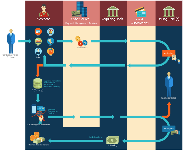
This payment process flowchart example was created on the base of the diagram of payment process using Global Payment Processing Services from the U.S. Securities and Exchange Commission website.
"Global Payment Processing Services. CyberSource Advanced enables merchants to accept payments made by all major credit and debit cards including American Express®, Discover®, Diners Club International®, JCB, MasterCard®, and Visa® cards. Our customers can also accept payment by corporate procurement cards, electronic checks, PayPal® Express Checkout, and the Bill Me Later® service. Merchants that have business models based on subscriptions can utilize the CyberSource recurring billing service with automated account updating services. For merchants selling internationally, we support direct debit, and bank transfers, as well as regional card brands such as Carte Bleue, Carta Si, Dankort, Laser, Solo, and Visa Electron. We provide these services for online, call center, kiosk, integrated voice response (“IVR”), and IP-enabled point of sale (“POS”) transactions."
[www.sec.gov/ Archives/ edgar/ data/ 934280/ 000119312510042764/ d10k.htm]
The flowchart example "Global Payment Solutions" was created using the ConceptDraw PRO diagramming and vector drawing software extended with the Sales Flowcharts solution from the Marketing area of ConceptDraw Solution Park.
Payment process flowchart
 Enterprise Architecture Diagrams
Enterprise Architecture Diagrams solution extends ConceptDraw PRO software with templates, samples and library of vector stencils for drawing the diagrams of enterprise architecture models.
Cisco Network Objects in ConceptDraw PRO

Six Markets Model Chart

The six markets model defines six markets that take the central place in the relationship marketing: internal markets, supplier markets, recruitment markets, referral markets, influence markets and customer markets. The six markets model allows the organization to analyze the stakeholders and key market domains that can be important to it.
HelpDesk
How to Create a Network Layout Floor Plan

HelpDesk
How To Convert a Telecommunication Network Diagram to Adobe PDF Using ConceptDraw PRO

HelpDesk
How to Make Network Diagram

HelpDesk
How to Add a Telecommunication Network Diagram to a MS Word Document Using ConceptDraw PRO

HelpDesk
How to Create a Cloud Computing Diagram Using ConceptDraw PRO

ConceptDraw's Cloud Computing Diagrams solution allows you to visualize cloud computing models of any configuration and complexity.
HelpDesk
How to Create a Computer Network Diagram in ConceptDraw PRO

With the Conceptdraw solution for Computer Network Diagrams, system administrators, network architects and other related IT specialists have a perfect drawing tool that supplies adjective vector stencils representing hardware, telecom devices, and logical symbols that enhance possibilities in network diagramming, however complex the real network may be.
HelpDesk
How to Create Cisco Network Diagram Using ConceptDraw Libraries

UML Class Diagram Generalization Example UML Diagrams

This sample describes the use of the classes, the generalization associations between them, the multiplicity of associations and constraints. Provided UML diagram is one of the examples set that are part of Rapid UML solution.
- IVR time auto-attendant diagram | Sales symbols - Vector stencils ...
- IVR customer service hotline diagram | Leaky bucket diagram ...
- What is Interactive Flowcharts | How to Create a Sales Dashboard ...
- Interactive Voice Response Network Diagram | Network ...
- How to Create an Interactive Voice Response ( IVR ) Diagram in ...
- Interactive Voice Response Diagrams | IVR time auto-attendant ...
- Interactive Voice Response Diagrams | Interactive Venn Diagram ...
- IVR customer service hotline diagram | Process Flowchart | Example ...
- How to Create a Sales Dashboard Using ConceptDraw PRO ...
- IVR time auto-attendant diagram
- IVR flowchart - Store reporting | How to Create an Interactive Voice ...
- Copying Service Process Flowchart. Flowchart Examples | Process ...
- How to Create a Sales Dashboard Using ConceptDraw PRO | How ...
- What is Interactive Flowcharts | How to Create a Social Media DFD ...
- How to Create a Sales Dashboard Using ConceptDraw PRO | How ...
- Design Element: IVR for Network Diagrams | Interactive Voice ...
- IVR time auto-attendant diagram | Interactive Voice Response ...
- Network Diagramming Software for Design IVR Network Diagrams ...
- Design elements - Interactive voice response ( IVR ) | Cisco ...
- Organizational Charts | How to Use ConceptDraw Sales Dashboard ...
- ERD | Entity Relationship Diagrams, ERD Software for Mac and Win
- Flowchart | Basic Flowchart Symbols and Meaning
- Flowchart | Flowchart Design - Symbols, Shapes, Stencils and Icons
- Flowchart | Flow Chart Symbols
- Electrical | Electrical Drawing - Wiring and Circuits Schematics
- Flowchart | Common Flowchart Symbols
- Flowchart | Common Flowchart Symbols