The vector stencils library "Bank UML interaction overview diagram" contains 11 shapes for drawing UML interaction overview diagrams.
Use it for object-oriented modeling of your bank information system.
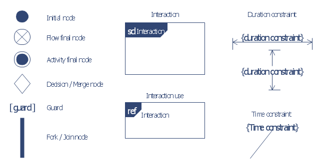
"The interaction overview diagram is similar to the activity diagram, in that both visualize a sequence of activities. The difference is that, for an interaction overview, each individual activity is pictured as a frame which can contain a nested interaction diagrams. ...
The other notation elements for interaction overview diagrams are the same as for activity diagrams. These include initial, final, decision, merge, fork and join nodes. The two new elements in the interaction overview diagrams are the "interaction occurrences" and "interaction elements"." [Interaction overview diagram. Wikipedia]
This example of UML interaction overview diagram symbols for the ConceptDraw PRO diagramming and vector drawing software is included in the ATM UML Diagrams solution from the Software Development area of ConceptDraw Solution Park.
Use it for object-oriented modeling of your bank information system.
"The interaction overview diagram is similar to the activity diagram, in that both visualize a sequence of activities. The difference is that, for an interaction overview, each individual activity is pictured as a frame which can contain a nested interaction diagrams. ...
The other notation elements for interaction overview diagrams are the same as for activity diagrams. These include initial, final, decision, merge, fork and join nodes. The two new elements in the interaction overview diagrams are the "interaction occurrences" and "interaction elements"." [Interaction overview diagram. Wikipedia]
This example of UML interaction overview diagram symbols for the ConceptDraw PRO diagramming and vector drawing software is included in the ATM UML Diagrams solution from the Software Development area of ConceptDraw Solution Park.
UML interaction overview diagram symbols
Use Case Diagrams technology with ConceptDraw PRO

HelpDesk
How to Create a Bank ATM Use Case Diagram

ConceptDraw PRO diagramming software, enhanced and expanded with the ATM UML Diagrams solution, offers the full range of icons, templates and design elements needed to faithfully represent ATM and banking information system architecture using UML standards. The ATM UML Diagrams solution is useful for beginner and advanced users alike. More experienced users will appreciate a full range of vector stencil libraries and ConceptDraw PRO's powerful software, that allows you to create your ATM UML diagram in a matter of moments.
- Interaction Diagram Of Bank Management System
- UML use case diagram - Banking system
- ATM UML Diagrams
- Bank Sequence Diagram | ATM UML Diagrams | UML Deployment ...
- Bank Sequence Diagram | UML Diagram | Banking System ...
- UML Sequence Diagram Example. SVG Vectored UML Diagrams ...
- Timing Diagram Bank System Uml
- UML use case diagram - Banking system | UML for Bank | Banking ...
- Bank Activity Diagram
- Bank Sequence Diagram
- Activity Diagram For Bank Atm
- UML use case diagram - Banking system | Banking System | UML for ...
- Uml Interaction Diagrams
- UML Deployment Diagram Example - ATM System UML diagrams ...
- UML Sequence Diagram
- Design elements - Bank UML sequence diagram | UML Deployment ...
- ATM UML Diagrams | How to Create a Bank ATM Use Case ...
- Design elements - UML interaction overview diagrams | Design ...
- Creating An Atm Machine In Interaction Design
- Diagramming Software for Design UML Interaction Overview Diagrams
- ERD | Entity Relationship Diagrams, ERD Software for Mac and Win
- Flowchart | Basic Flowchart Symbols and Meaning
- Flowchart | Flowchart Design - Symbols, Shapes, Stencils and Icons
- Flowchart | Flow Chart Symbols
- Electrical | Electrical Drawing - Wiring and Circuits Schematics
- Flowchart | Common Flowchart Symbols
- Flowchart | Common Flowchart Symbols