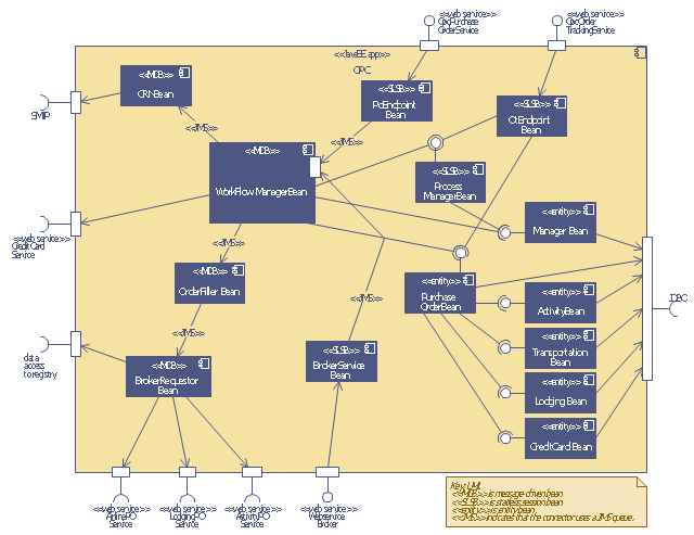
This UML sequence diagram of order processing center (OPC) was created on the base of sequence diagram from the software architecture documentation wiki of the Software Engineering Institute (SEI) of Carnegie Mellon University (CMU).
[wiki.sei.cmu.edu/ sad/ index.php/ Image:OPCRuntimeRefinementView_ PP2.png]
"Order processing is the process or work-flow associated with the picking, packing and delivery of the packed items to a shipping carrier. Order processing is a key element of order fulfillment. Order processing operations or facilities are commonly called "distribution centers"." [Order processing. Wikipedia]
This order processing center UML sequence diagram example was created using the ConceptDraw PRO diagramming and vector drawing software extended with the ATM UML Diagrams solution from the Software Development area of ConceptDraw Solution Park.
Order processing center UML sequence diagram
IDEF0 Flowchart Symbols

Cloud Computing Architecture Diagrams

Examples of Flowcharts, Org Charts and More


Stakeholder Onion Diagrams
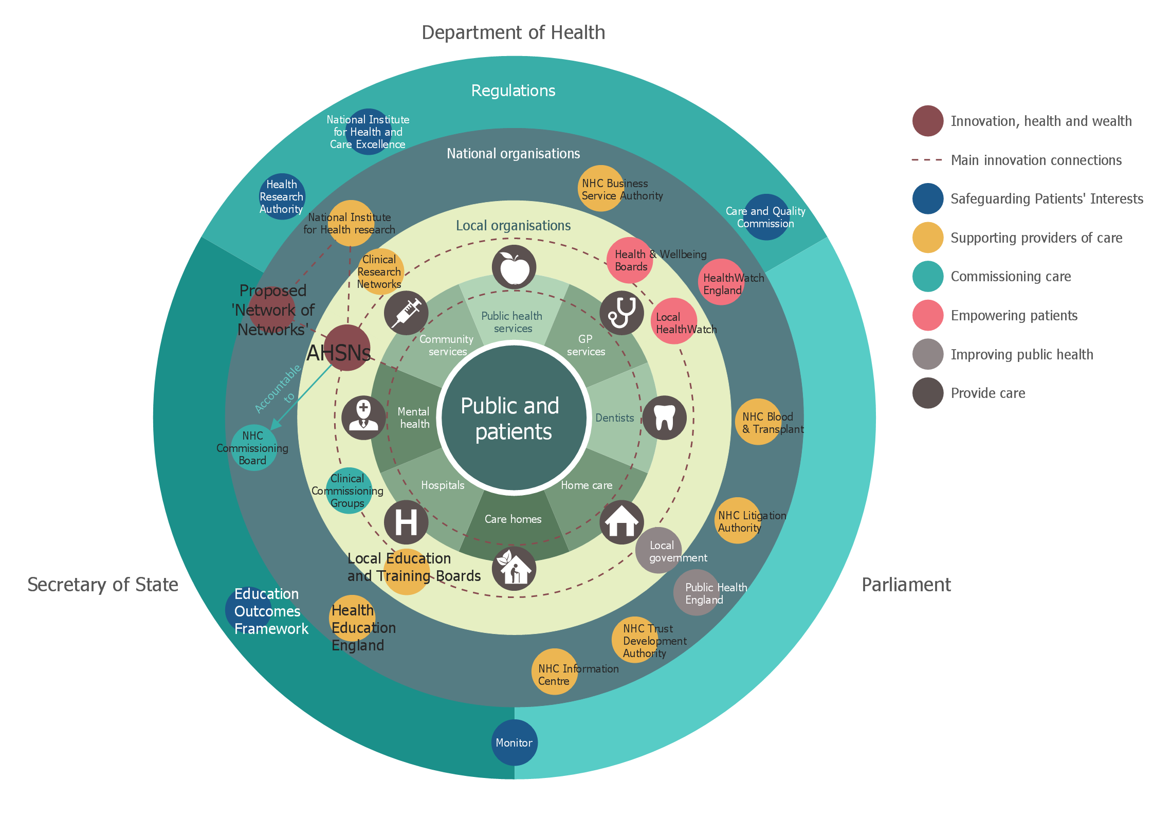
Design fast and easy Stakeholder Onion Diagrams of any complexity in ConceptDraw DIAGRAM diagramming and vector drawing software using the powerful tools of Stakeholder Onion Diagrams Solution from the Management Area of ConceptDraw Solution Park.
- Computer Institute Line Plan
- Order processing center - UML sequence diagram | Sequence ...
- UML Sequence Diagram | Diagramming Software for designing ...
- Order processing - Cross-functional flowchart | Order processing ...
- Pert Chart For Institute Management System Project
- Diagramming Software for designing UML Sequence Diagrams ...
- Bank Sequence Diagram | UML Use Case Diagram Example ...
- Order processing center - UML sequence diagram | Process ...
- Er Dygram In Institute Management System Project Pdf
- Order processing center - UML sequence diagram | Order process ...
- Work Order Process Flowchart. Business Process Mapping Examples
- Purchase order processing UML activity diagram | Bank ATM use ...
- Computer Institute Building Plans And Desings
- ATM Solutions | Order processing center - UML sequence diagram ...
- Process Flow Diagram Symbols | Program Evaluation and Review ...
- Purchase order processing UML activity diagram
- Order Form Software
- Ordering Process Flowchart. Flowchart Examples | Work Order ...
- UML Sequence Diagram | Diagramming Software for designing ...
- Event-driven Process Chain Diagrams | Purchase order processing ...
- ERD | Entity Relationship Diagrams, ERD Software for Mac and Win
- Flowchart | Basic Flowchart Symbols and Meaning
- Flowchart | Flowchart Design - Symbols, Shapes, Stencils and Icons
- Flowchart | Flow Chart Symbols
- Electrical | Electrical Drawing - Wiring and Circuits Schematics
- Flowchart | Common Flowchart Symbols
- Flowchart | Common Flowchart Symbols