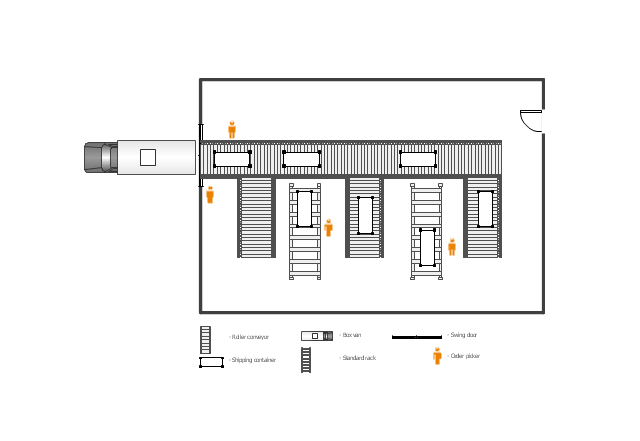
This floor plan example was drawn on the base of slide 27 "Warehouse Layout Floor Plan" of the presentation "Operations Management. Layout Strategy. Chapter 9" from the website of the School of Business Administration at Portland State University. [sba.pdx.edu/ faculty/ karlt/ Ch9/ sld027.htm]
"A conveyor system is a common piece of mechanical handling equipment that moves materials from one location to another. Conveyors are especially useful in applications involving the transportation of heavy or bulky materials. Conveyor systems allow quick and efficient transportation for a wide variety of materials, which make them very popular in the material handling and packaging industries. Many kinds of conveying systems are available, and are used according to the various needs of different industries. There are chain conveyors (floor and overhead) as well. Chain conveyors consist of enclosed tracks, I-Beam, towline, power & free, and hand pushed trolleys." [Conveyor system. Wikipedia]
The floor plan example "Warehouse with conveyor system" was created using the ConceptDraw PRO diagramming and vector drawing software extended with the Plant Layout Plans solution from the Building Plans area of ConceptDraw Solution Park.
Floor plan - Warehouse with conveyor system
 Plant Layout Plans
This solution extends ConceptDraw PRO v.9.5 plant layout software (or later) with process plant layout and piping design samples, templates and libraries of vector stencils for drawing Plant Layout plans. Use it to develop plant layouts, power plant desig
Mac Diagramming Software

 Rack Diagrams
Rack Diagrams solution extends ConceptDraw PRO software with samples, templates and libraries of vector stencils for drawing the computer network server rack mounting diagrams.
The vector stencils library "Machines and equipment" contains 24 symbols of industrial machines and equipment.
Use the design elements library "Machines and equipment" for drawing plant interior design plans, manufacturing equipment layouts and factory floor plans using the ConceptDraw PRO diagramming and vector drawing software.
"Manufacturing is the production of goods for use or sale using labor and machines, tools, chemical and biological processing, or formulation. The term may refer to a range of human activity, from handicraft to high tech, but is most commonly applied to industrial production, in which raw materials are transformed into finished goods on a large scale.
Modern manufacturing includes all intermediate processes required for the production and integration of a product's components. Some industries, such as semiconductor and steel manufacturers use the term fabrication instead.
The manufacturing sector is closely connected with engineering and industrial design." [Manufacturing. Wikipedia]
The shapes library "Machines and equipment" is included in the Plant Layout Plans solution from the Building Plans area of ConceptDraw Solution Park.
Machines and equipment symbols

 Audit Flowcharts
Audit flowcharts solution extends ConceptDraw PRO software with templates, samples and library of vector stencils for drawing the audit and fiscal flow charts.
HelpDesk
How to Draw a Chemical Process Flow Diagram

 Fishbone Diagrams
The Fishbone Diagrams solution extends ConceptDraw PRO v10 software with the ability to easily draw the Fishbone Diagrams (Ishikawa Diagrams) to clearly see the cause and effect analysis and also problem solving. The vector graphic diagrams produced using this solution can be used in whitepapers, presentations, datasheets, posters, and published technical material.
 Specification and Description Language (SDL)
For people in the field of systems engineering or system design, working with specification and description language (sdl) and finite state machines (fsm).
- Industrial Building Floor Plans
- Factory layout floor plan | Plant Layout Plans | Building Drawing ...
- Factory layout floor plan | Plant Layout Plans | Restaurant Floor ...
- Industrial Floor Plan Design
- Plant Layout Plans | Factory layout floor plan | How to Create a Plant ...
- Plant Layout Plans | Factory layout floor plan | Store Layout Software ...
- Industrial Floor Plan
- Plant Layout Plans | Factory layout floor plan | Interior Design ...
- Factory layout floor plan | Interior Design Machines and Equipment ...
- Manufacturing Floor Plan Layout
- Warehouse with conveyor system - Floor plan | Plant Layout Plans ...
- Industries Floor Plans Com
- Industries Floor Plan
- Warehouse layout floor plan | Plant Layout Plans | Warehouse with ...
- Restaurant Floor Plans Samples | Plant Layout Plans | Factory ...
- Floor Plan Of Juice Production Factories Industries
- Warehouse with conveyor system - Floor plan | Interior Design ...
- Plant Layout Plans | Factory layout floor plan | Building Drawing ...
- Plant Layout Plans | Factory layout floor plan | How to Create a Plant ...
- Process Flowchart | Warehouse with conveyor system - Floor plan ...
- ERD | Entity Relationship Diagrams, ERD Software for Mac and Win
- Flowchart | Basic Flowchart Symbols and Meaning
- Flowchart | Flowchart Design - Symbols, Shapes, Stencils and Icons
- Flowchart | Flow Chart Symbols
- Electrical | Electrical Drawing - Wiring and Circuits Schematics
- Flowchart | Common Flowchart Symbols
- Flowchart | Common Flowchart Symbols