"Deployment diagram shows execution architecture of systems that represent the assignment (deployment) of software artifacts to deployment targets (usually nodes).
Nodes represent either hardware devices or software execution environments. They could be connected through communication paths to create network systems of arbitrary complexity. Artifacts represent concrete elements in the physical world that are the result of a development process and are deployed on nodes.
Note, that components were directly deployed to nodes in UML 1.x deployment diagrams. In UML 2.x artifacts are deployed to nodes, and artifacts could manifest (implement) components. So components are now deployed to nodes indirectly through artifacts." [uml-diagrams.org/ deployment-diagrams.html]
The template "UML deployment diagram" for the ConceptDraw PRO diagramming and vector drawing software is included in the Rapid UML solution from the Software Development area of ConceptDraw Solution Park.
www.conceptdraw.com/ solution-park/ software-uml
UML deployment diagram

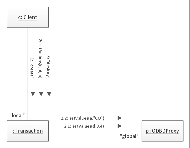
"Communication diagram (called collaboration diagram in UML 1.x) is a kind of UML interaction diagram which shows interactions between objects and/ or parts (represented as lifelines) using sequenced messages in a free-form arrangement.
Communication diagram corresponds (i.e. could be converted to/ from or replaced by) to a simple sequence diagram without structuring mechanisms such as interaction uses and combined fragments. It is also assumed that message overtaking (i.e., the order of the receptions are different from the order of sending of a given set of messages) will not take place or is irrelevant." [uml-diagrams.org/ communication-diagrams.html]
The template "UML communication diagram" for the ConceptDraw PRO diagramming and vector drawing software is included in the Rapid UML solution from the Software Development area of ConceptDraw Solution Park.
www.conceptdraw.com/ solution-park/ software-uml
UML communication diagram
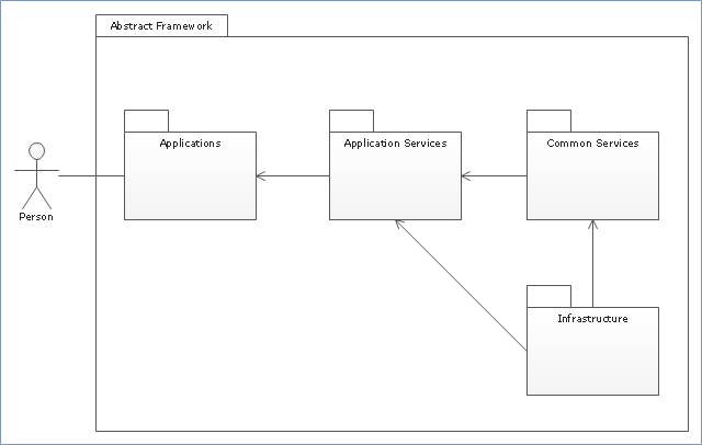
"Package diagram is UML structure diagram which shows packages and dependencies between the packages.
Model diagrams allow to show different views of a system, for example, as multi-layered (aka multi-tiered) application - multi-layered application model.
The following nodes and edges are typically drawn in a package diagram: package, packageable element, dependency, element import, package import, package merge." [uml-diagrams.org/ package-diagrams.html]
The template "UML package diagram" for the ConceptDraw PRO diagramming and vector drawing software is included in the Rapid UML solution from the Software Development area of ConceptDraw Solution Park.
www.conceptdraw.com/ solution-park/ software-uml
UML package diagram
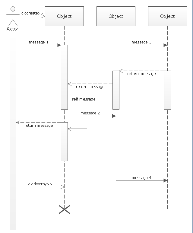
"Sequence diagram is the most common kind of interaction diagram, which focuses on the message interchange between a number of lifelines.
Sequence diagram describes an interaction by focusing on the sequence of messages that are exchanged, along with their corresponding occurrence specifications on the lifelines.
The following nodes and edges are typically drawn in a UML sequence diagram: lifeline, execution specification, message, combined fragment, interaction use, state invariant, continuation, destruction occurrence." [uml-diagrams.org/ sequence-diagrams.html]
The template "UML sequence diagram" for the ConceptDraw PRO diagramming and vector drawing software is included in the Rapid UML solution from the Software Development area of ConceptDraw Solution Park.
www.conceptdraw.com/ solution-park/ software-uml
UML sequence diagram
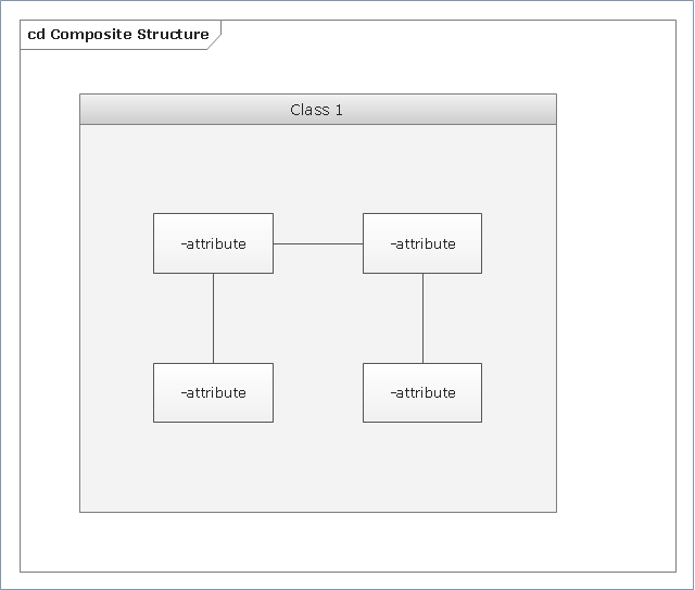
"Composite Structure Diagram could be used to show:
(1) internal structure of a classifier - internal structure diagram,
(2) classifier interactions with environment through ports,
(3) a behavior of a collaboration - collaboration use diagram.
The term "structure" for this type of diagrams is defined in UML as a composition of interconnected elements, representing run-time instances collaborating over communications links to achieve some common objectives." [uml-diagrams.org/ composite-structure-diagrams.html]
The template "UML composite structure diagram" for the ConceptDraw PRO diagramming and vector drawing software is included in the Rapid UML solution from the Software Development area of ConceptDraw Solution Park.
www.conceptdraw.com/ solution-park/ software-uml
UML composite structure diagram
"Component diagram shows components, provided and required interfaces, ports, and relationships between them. This type of diagrams is used in Component-Based Development (CBD) to describe systems with Service-Oriented Architecture (SOA).
Component-based development is based on assumptions that previously constructed components could be reused and that components could be replaced by some other "equivalent" or "conformant" components, if needed.
The artifacts that implement component are intended to be capable of being deployed and re-deployed independently, for instance to update an existing system.
Components in UML could represent:
(1) logical components (e.g., business components, process components), and
(2) physical components (e.g., CORBA components, EJB components, COM+ and .NET components, WSDL components, etc.),
along with the artifacts that implement them and the nodes on which they are deployed and executed. It is anticipated that profiles based around components will be developed for specific component technologies and associated hardware and software environments." [uml-diagrams.org/ component-diagrams.html]
The template "UML component diagram" for the ConceptDraw PRO diagramming and vector drawing software is included in the Rapid UML solution from the Software Development area of ConceptDraw Solution Park.
www.conceptdraw.com/ solution-park/ software-uml
UML component diagram

"State machine diagram is a behavior diagram which shows discrete behavior of a part of designed system through finite state transitions. State machine diagrams can also be used to express the usage protocol of part of a system. Two kinds of state machines defined in UML 2.4 are:
(1) behavioral state machine, and
(2) protocol state machine.
The following nodes and edges are typically drawn in state machine diagram: behavioral state, behavioral transition, protocol state, protocol transition, different pseudostates. ...
Behavioral state machine is specialization of behavior and is used to specify discrete behavior of a part of designed system through finite state transitions. The state machine formalism used in this case is an object-based variant of Harel statecharts.
Behavior is modeled as a traversal of a graph of state nodes connected with transitions. Transitions are triggered by the dispatching of series of events. During the traversal, the state machine could also execute some activities. ...
Protocol state machine is a specialization of behavioral state machine and is used to express usage protocol or lifecycle of a classifier. It specifies which operations of the classifier can be called in which state and under which condition, thus specifying the allowed call sequences on the classifier’s operations. Protocol state machines express the legal transitions that a classifier can trigger." [uml-diagrams.org/ state-machine-diagrams.html]
The template "UML state machine diagram" for the ConceptDraw PRO diagramming and vector drawing software is included in the Rapid UML solution from the Software Development area of ConceptDraw Solution Park.
www.conceptdraw.com/ solution-park/ software-uml
UML state machine diagram

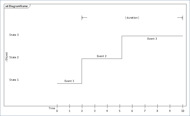
"Timing diagrams are UML interaction diagrams used to show interactions when a primary purpose of the diagram is to reason about time. Timing diagrams focus on conditions changing within and among lifelines along a linear time axis. Timing diagrams describe behavior of both individual classifiers and interactions of classifiers, focusing attention on time of events causing changes in the modeled conditions of the lifelines.
The following nodes and edges are typically drawn in a UML timing diagram: lifeline, state or condition timeline, destruction event, duration constraint, time constraint." [uml-diagrams.org/ timing-diagrams.html]
The template "UML timing diagram" for the ConceptDraw PRO diagramming and vector drawing software is included in the Rapid UML solution from the Software Development area of ConceptDraw Solution Park.
www.conceptdraw.com/ solution-park/ software-uml
UML timing diagram
The vector stencils library "UML use case diagrams" contains 25 symbols for the ConceptDraw PRO diagramming and vector drawing software.
"Use case diagrams are usually referred to as behavior diagrams used to describe a set of actions (use cases) that some system or systems (subject) should or can perform in collaboration with one or more external users of the system (actors). Each use case should provide some observable and valuable result to the actors or other stakeholders of the system. ...
Use case diagrams are in fact twofold - they are both behavior diagrams, because they describe behavior of the system, and they are also structure diagrams - as a special case of class diagrams where classifiers are restricted to be either actors or use cases related to each other with associations. ...
Use case is usually shown as an ellipse containing the name of the use case. ...
Name of the use case could also be placed below the ellipse. ...
If a subject (or system boundary) is displayed, the use case ellipse is visually located inside the system boundary rectangle. Note, that this does not necessarily mean that the subject classifier owns the contained use cases, but merely that the use case applies to that classifier. ...
A list of use case properties - operations and attributes - could be shown in a compartment within the use case oval below the use case name. ...
Use case with extension points may be listed in a compartment of the use case with the heading extension points. ...
A use case can also be shown using the standard rectangle notation for classifiers with an ellipse icon in the upper right-hand corner of the rectangle and with optional separate list compartments for its features. ...
Subject (sometimes called a system boundary) is presented by a rectangle with subject's name, associated keywords and stereotypes in the upper left corner. Use cases applicable to the subject are located inside the rectangle and actors - outside of the system boundary. ...
Standard UML notation for actor is "stick man" icon with the name of the actor above or below of the icon. Actor names should follow the capitalization and punctuation guidelines for classes. The names of abstract actors should be shown in italics. ...
Custom icons that convey the kind of actor may also be used to denote an actor, such as using a separate icon(s) for non-human actors. ...
An actor may also be shown as a class rectangle with the standard keyword «actor», having usual notation for class compartments ...
An actor can only have binary associations to use cases, components, and classes. ...
An association between an actor and a use case indicates that the actor and the use case somehow interact or communicate with each other.
Only binary associations are allowed between actors and use cases.
An actor could be associated to one or several use cases. ...
A use case may have one or several associated actors." [uml-diagrams.org/ use-case-diagrams.html]
The example "Design elements - UML use case diagrams" is included in the Rapid UML solution from the Software Development area of ConceptDraw Solution Park.
UML use case diagram symbols

The vector stencils library "UML timing diagrams" contains 15 symbols for the ConceptDraw PRO diagramming and vector drawing software.
"The following nodes and edges are typically drawn in a UML timing diagram: lifeline, state or condition timeline, destruction event, duration constraint, time constraint. ...
Lifeline is a named element which represents an individual participant in the interaction. ... lifelines represent only one interacting entity. ...
Lifeline on the timing diagrams is represented by the name of classifier or the instance it represents. It could be placed inside diagram frame or a "swimlane". ...
Timing diagram could show states of the participating classifier or attribute, or some testable conditions, such as a discrete or enumerable value of an attribute. ...
UML also allows the state/ condition dimension be continuous. It could be used in scenarios where entities undergo continuous state changes, such as temperature or density. ...
Destruction occurrence is a message occurrence which represents the destruction of the instance described by the lifeline. It may result in the subsequent destruction of other objects that this object owns by composition. No other occurrence may appear after the destruction event on a given lifeline.
Complete UML name of the occurrence is destruction occurrence specification. Until UML 2.4 it was called destruction event, and earlier - stop.
The destruction event is depicted by a cross in the form of an X at the end of a timeline. ...
Duration constraint is an interval constraint that refers to a duration interval. The duration interval is duration used to determine whether the constraint is satisfied.
The semantics of a duration constraint is inherited from constraints. If constraints are violated, traces become negative which means that system is considered as failed.
Duration constraint is shown as some graphical association between a duration interval and the constructs that it constrains. ...
Time constraint is an interval constraint that refers to a time interval. The time interval is time expression used to determine whether the constraint is satisfied.
The semantics of a time constraint is inherited from constraints. All traces where the constraints are violated are negative traces, i.e., if they occur, the system is considered as failed.
Time constraint is shown as graphical association between a time interval and the construct that it constrains. Typically this graphical association is a small line, e.g., between an occurrence specification and a time interval." [uml-diagrams.org/ timing-diagrams.html]
The example "Design elements - UML timing diagrams" is included in the Rapid UML solution from the Software Development area of ConceptDraw Solution Park.
UML timing diagram symbols

This bank account UML package diagram was redesigned from the Wikimedia Commons file: Package diagram1.jpg.
[commons.wikimedia.org/ wiki/ File:Package_ diagram1.jpg]
This file is licensed under the Creative Commons Attribution-Share Alike 3.0 Unported license. [creativecommons.org/ licenses/ by-sa/ 3.0/ deed.en]
"A very important concept in object-oriented design, inheritance, refers to the ability of one class (child class) to inherit the identical functionality of another class (super class), and then add new functionality of its own. (In a very non-technical sense, imagine that I inherited my mother's general musical abilities, but in my family I'm the only one who plays electric guitar.) To model inheritance on a class diagram, a solid line is drawn from the child class (the class inheriting the behavior) with a closed, unfilled arrowhead (or triangle) pointing to the super class. Consider types of bank accounts: Figure 4 shows how both CheckingAccount and SavingsAccount classes inherit from the BankAccount class.
Figure 4: Inheritance is indicated by a solid line with a closed, unfilled arrowhead pointing at the super class." [ibm.com/ developerworks/ rational/ library/ content/ RationalEdge/ sep04/ bell/ index.html]
This bank account UML package diagram example was created using the ConceptDraw PRO diagramming and vector drawing software extended with the ATM UML Diagrams solution from the Software Development area of ConceptDraw Solution Park.
Bank account UML package diagram

UML Software

The Rapid UML Solution for ConceptDraw PRO presentsthe intuitive RapidDraw interface that helps you to make the UML Diagram of any of these 13 types quick and easy.
UML Diagram Software
 Diagram")
UML for Software Engineers

UML Diagram Tool

Programming with UML

Process with UML

This sample was created in ConceptDraw PRO diagramming and vector drawing software using the Rapid UML Solution from the Software Development area of ConceptDraw Solution Park.
Professionally Designed UML Diagram Examples

It’s very simple, convenient and quick to design professional looking UML Diagrams of any complexity using the Rapid UML Solution that provides a wide set of predesigned objects, templates and samples.
UML Class Diagram Notation

Database Diagram Tool

- UML package diagram - Template | UML communication diagram ...
- UML interaction overview diagram - Online shopping | UML ...
- Organizational Chart Templates | UML composite structure diagram ...
- Diagramming Software for Design UML Interaction Overview Diagrams
- Timing diagram | UML timing diagram - Template | Diagramming ...
- UML Component Diagram | Flowchart Component | UML ...
- Diagramming Software for Design UML Package Diagrams | UML ...
- Diagramming Software for Design UML Collaboration Diagrams ...
- UML Deployment Diagram
- UML Component Diagram | Diagramming Software for Design UML ...
- Diagramming Software for designing UML Sequence Diagrams ...
- Basic Flowchart Symbols and Meaning | Design elements - UML ...
- Diagramming Software for UML Composite Structure Diagrams ...
- Diagramming Software for Design UML State Machine Diagrams ...
- UML State Machine Diagram.Design Elements | UML Diagram ...
- UML state machine diagram - Template | How to Use ConceptDraw ...
- Timing diagram | Diagramming Software for Design UML Timing ...
- Data structure diagram with ConceptDraw PRO | UML Composite ...
- Design elements - UML state machine diagrams | Design elements ...
- UML Sequence Diagram. Design Elements | Sequence Diagram ...
- ERD | Entity Relationship Diagrams, ERD Software for Mac and Win
- Flowchart | Basic Flowchart Symbols and Meaning
- Flowchart | Flowchart Design - Symbols, Shapes, Stencils and Icons
- Flowchart | Flow Chart Symbols
- Electrical | Electrical Drawing - Wiring and Circuits Schematics
- Flowchart | Common Flowchart Symbols
- Flowchart | Common Flowchart Symbols