How To use House Electrical Plan Software

You can use many of built-in templates, electrical symbols and electical schemes examples of our House Electrical Diagram Software.
ConceptDraw is a fast way to draw: Electrical circuit diagrams, Schematics, Electrical Wiring, Circuit schematics, Digital circuits, Wiring in buildings, Electrical equipment, House electrical plans, Home cinema, Satellite television, Cable television, Closed-circuit television.
House Electrical Plan Software works across any platform, meaning you never have to worry about compatibility again. ConceptDraw PRO allows you to make electrical circuit diagrams on PC or macOS operating systems.

 Plant Layout Plans
This solution extends ConceptDraw PRO v.9.5 plant layout software (or later) with process plant layout and piping design samples, templates and libraries of vector stencils for drawing Plant Layout plans. Use it to develop plant layouts, power plant desig
How Do Fishbone Diagrams Solve Manufacturing Problems

ConceptDraw PRO application extended with Fishbone Diagrams solution lets you construct Fishbone diagrams and represent globally recognized standards for manufacturing 6 Ms and 8 Ms.
 Fishbone Diagrams
The Fishbone Diagrams solution extends ConceptDraw PRO v10 software with the ability to easily draw the Fishbone Diagrams (Ishikawa Diagrams) to clearly see the cause and effect analysis and also problem solving. The vector graphic diagrams produced using this solution can be used in whitepapers, presentations, datasheets, posters, and published technical material.
Interior Design Machines and Equipment - Design Elements

Electrical Schematic

F&B

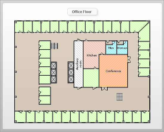
How To Draw Building Plans

Quick building plan software for creating great-looking office layout, home floor, electrical plan, commercial floor plans, Storage building plans, expo and shopping mall building plans, school and training building plans, cafe or restaurant plans, gym and spa area plans, sport field plans, electric and telecom building plans, fire and emergency plans, HVAC plans, security and access plans, plumbing and piping plans and plant layouts.

Electrical Symbols — Semiconductor Diodes

26 libraries of the Electrical Engineering Solution of ConceptDraw PRO make your electrical diagramming simple, efficient, and effective. You can simply and quickly drop the ready-to-use objects from libraries into your document to create the electrical diagram.
How To Create Floor Plans
- Electrical Sample Of Drink Production Factory Layout
- Emergency Plan | Plant Layout Plans | Restaurant Floor Plans ...
- How to Create a Residential Plumbing Plan | Plumbing and Piping ...
- Plant Layout Plans | Emergency Plan Template | Plant Design ...
- Chemical and Process Engineering | How to Draw a Chemical ...
- Process Flowchart | Process Flow Diagram Symbols | Electrical ...
- Energy resources diagram | Landscape Plan | Healthy Diet Plan ...
- Chemical Engineering Symbols Drawing
- How To use House Electrical Plan Software | Electrical Symbols ...
- Equipments And Their Symbols In Chemical Industry
- ERD | Entity Relationship Diagrams, ERD Software for Mac and Win
- Flowchart | Basic Flowchart Symbols and Meaning
- Flowchart | Flowchart Design - Symbols, Shapes, Stencils and Icons
- Flowchart | Flow Chart Symbols
- Electrical | Electrical Drawing - Wiring and Circuits Schematics
- Flowchart | Common Flowchart Symbols
- Flowchart | Common Flowchart Symbols