Electrical Symbols, Electrical Diagram Symbols

This solution provides 26 libraries which contain 926 electrical symbols from electrical engineering: Analog and Digital Logic, Composite Assemblies, Delay Elements, Electrical Circuits, Electron Tubes, IGFET, Inductors, Integrated Circuit, Lamps, Acoustics, Readouts, Logic Gate Diagram, MOSFET, Maintenance, Power Sources, Qualifying, Resistors, Rotating Equipment, Semiconductor Diodes, Semiconductors, Stations, Switches and Relays, Terminals and Connectors, Thermo, Transformers and Windings, Transistors, Transmission Paths,VHF UHF SHF.
Home Electrical Plan

ConceptDraw Arrows10 Technology

Connection points are necessary for diagramming network, flowchart and organizational charts. In ConceptDraw you connect shapes by attaching, or snapping and gluing, connectors to shape connection points.
Wiring Diagrams with ConceptDraw DIAGRAM

Network Diagram Software

Our network drawing software has numerous network design diagram examples and templates:
GPRS Network Scheme,
GPS Operation Diagram,
Hybrid Network Diagram,
Mobile Satellite Communication Network,
Mobile TV Network Diagram,
Web-based Network Diagram,
Wireless Broadband Network Diagram,
Wireless Router Network Diagram.
You can use the more than 2 000 pre-designed stencils for making custom network diagrams.

Electrical Symbols — Terminals and Connectors

26 libraries of the Electrical Engineering Solution of ConceptDraw DIAGRAM make your electrical diagramming simple, efficient, and effective. You can simply and quickly drop the ready-to-use objects from libraries into your document to create the electrical diagram.
Electrical Symbols — Maintenance

The diagrams are a big help when workers try to find out why a circuit does not work correctly.
26 libraries of the Electrical Engineering Solution of ConceptDraw DIAGRAM make your electrical diagramming simple, efficient, and effective. You can simply and quickly drop the ready-to-use objects from libraries into your document to create the electrical diagram.
Network wiring cable. Computer and Network Examples

This example was created in ConceptDraw DIAGRAM using the Computer and Networks solution from the Computer and Networks area of ConceptDraw Solution Park.
Electrical Symbols — Switches and Relays

26 libraries of the Electrical Engineering Solution of ConceptDraw DIAGRAM make your electrical diagramming simple, efficient, and effective. You can simply and quickly drop the ready-to-use objects from libraries into your document to create the electrical diagram.
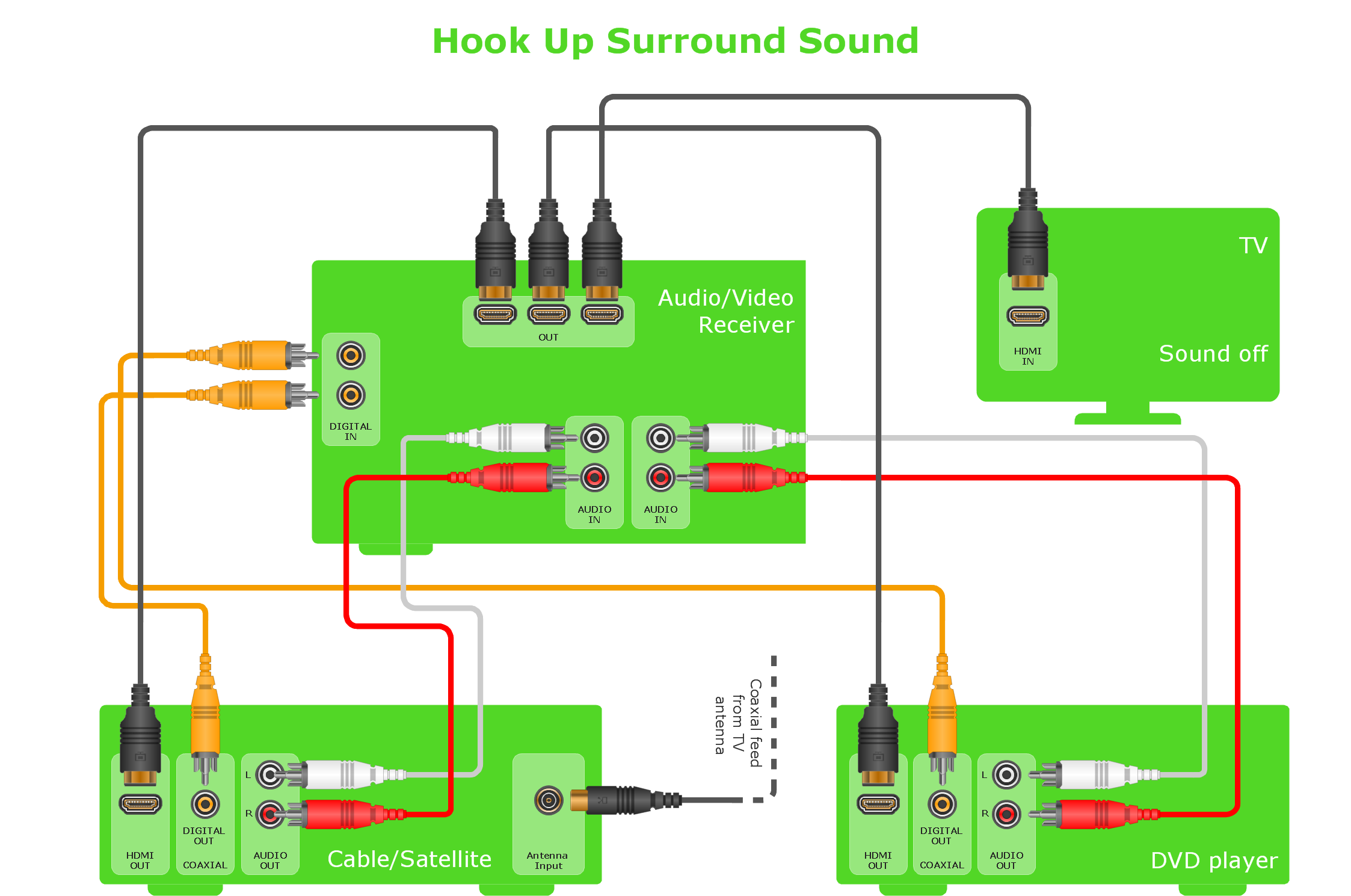
Audio & Video Connector Types
- Home Electrical Wiring Images Common
- Image Of Sample Building With Electrical Wiring Installation
- Electrical Symbols, Electrical Diagram Symbols | How To use House ...
- Lighting and switch layout | Classroom lighting - Reflected ceiling ...
- Marriage Hall Electrical Wiring Digse
- Image Of Two Bedroom Flat Electrical Wiring
- Power socket outlet layout
- How To use House Electrical Plan Software | Audio and Video ...
- Home Electrical Plan | How To use House Electrical Plan Software ...
- Cable Layout Diagram Sample
- ERD | Entity Relationship Diagrams, ERD Software for Mac and Win
- Flowchart | Basic Flowchart Symbols and Meaning
- Flowchart | Flowchart Design - Symbols, Shapes, Stencils and Icons
- Flowchart | Flow Chart Symbols
- Electrical | Electrical Drawing - Wiring and Circuits Schematics
- Flowchart | Common Flowchart Symbols
- Flowchart | Common Flowchart Symbols