UML Deployment Diagram. Diagramming Software for Design UML Diagrams


UML Deployment Diagram. Design Elements

ConceptDraw has 393 vector stencils in the 13 libraries that helps you to start using software for designing your own UML Diagrams. You can use the appropriate stencils of UML notation from UML Deployment library.
UML Deployment Diagram
Use ConceptDraw DIAGRAM with UML deployment diagram templates, samples and stencil library from Rapid UML solution to model the physical deployment of artifacts on nodes of your software system.
Deployment Chart Software
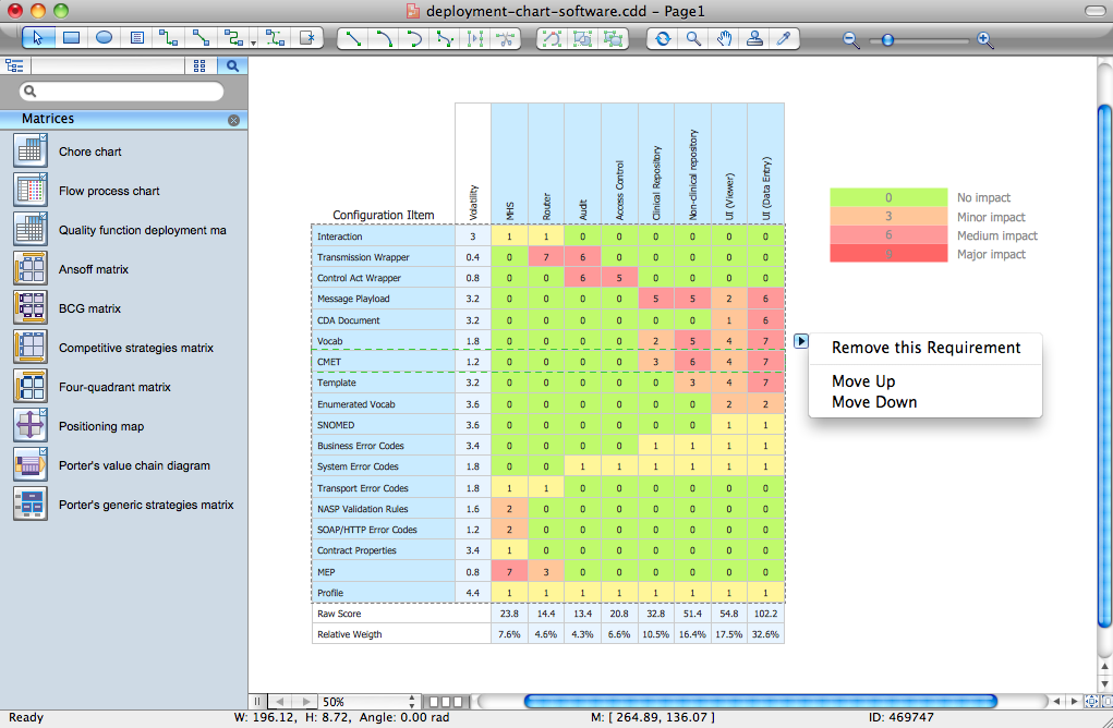
The Matrices solution offers you the useful tools for creating Deployment Charts in just minutes.
The Deployment Charts designed with ConceptDraw DIAGRAM are vector graphic documents and are available for reviewing, modifying, converting to a variety of formats (image, HTML, PDF file, MS PowerPoint Presentation, Adobe Flash or MS Visio XML), printing and send via e-mail in one moment.
UML Deployment Diagram Example - ATM System UML diagrams

This sample shows the work of the ATM (Automated Teller Machine) banking system that is used for service and performing of the banking transactions using ATMs. System engineers can use comprehensive UML diagrams solution.
Cloud Computing Architecture Diagrams

Software for Drawing EPC Diagrams
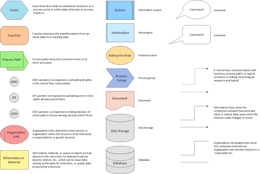
ConceptDraw DIAGRAM - software that reduces the time needed to create a business process model.
Diagramming Software for Design UML Component Diagrams

ConceptDraw Rapid UML solution delivers libraries contain pre-designed objects fit UML notation, and ready to draw professional UML Component Diagram.
UML Component Diagram

UML Component for Bank

UML Flowchart Symbols

The Rapid UML solution for ConceptDraw DIAGRAM software offers diversity of UML flowchart symbols for drawing all types of UML diagrams.
UML Diagramming Software

UML Diagrams with ConceptDraw DIAGRAM

ConceptDraw DIAGRAM is a software that provides possibility of detailed UML diagrams. A large number of stencils that coresponds to UML diagram notation and task-oriented templates.
Network Diagram Software. LAN Network Diagrams. Physical Office Network Diagrams


Introductory Guide to Rapid UML Solution

- Hardware Software Mapping Deployment
- Online Shopping Hardware Software Mapping
- Draw A Mind Map Of Hardware And Software
- Process Flowchart | Deployment Chart Software | Computer ...
- Online Shopping Hardware Software Mapping Example
- Hardware And Software Mind Map
- Template For Hardware Components
- Draw Diagram Hardware And Software Components
- Hardware Components Required For Mapping With Examples
- Hardware And Software Diagram
- How To Make A Chart On Hardware And Software
- Is Flowchart A Hardware Or Software
- Examples Of Software And Hardware
- UML Deployment Diagram Example
- Flowchart Of Hardware And Software
- Deployment Chart Software | Deployment chart - Template | UML ...
- Draw A Hardware Chart
- Hardware Software Complex Icon
- Software Deployment Process Diagram
- Map Mapping Hardware
- ERD | Entity Relationship Diagrams, ERD Software for Mac and Win
- Flowchart | Basic Flowchart Symbols and Meaning
- Flowchart | Flowchart Design - Symbols, Shapes, Stencils and Icons
- Flowchart | Flow Chart Symbols
- Electrical | Electrical Drawing - Wiring and Circuits Schematics
- Flowchart | Common Flowchart Symbols
- Flowchart | Common Flowchart Symbols