HelpDesk
How to Draw Geometric Shapes in ConceptDraw PRO

Mathematical Diagrams

Mathematics solution provides 3 libraries: Plane Geometry Library, Solid Geometry Library, Trigonometric Functions Library.
Mathematics Symbols

Mathematics solution provides 3 libraries with predesigned vector mathematics symbols and figures:
Solid Geometry Library, Plane Geometry Library and Trigonometric Functions Library.
This engineering drawing shows different types of geometry of butt welds.
"Welds can be geometrically prepared in many different ways. The five basic types of weld joints are the butt joint, lap joint, corner joint, edge joint, and T-joint (a variant of this last is the cruciform joint). Other variations exist as well - for example, double-V preparation joints are characterized by the two pieces of material each tapering to a single center point at one-half their height. Single-U and double-U preparation joints are also fairly common - instead of having straight edges like the single-V and double-V preparation joints, they are curved, forming the shape of a U. Lap joints are also commonly more than two pieces thick - depending on the process used and the thickness of the material, many pieces can be welded together in a lap joint geometry." [Welding. Wikipedia]
This engineering drawing example was redesigned using the ConceptDraw PRO diagramming and vector drawing software from the Wikimedia Commons file: Butt Weld Geometry.GIF.
[commons.wikimedia.org/ wiki/ File:Butt_ Weld_ Geometry.GIF]
The engineering drawing example "Butt weld geometry" is included in the Mechanical Engineering solution from the Engineering area of ConceptDraw Solution Park.
Welding joint diagram

 Mathematics
Mathematics solution extends ConceptDraw PRO software with templates, samples and libraries of vector stencils for drawing the mathematical illustrations, diagrams and charts.
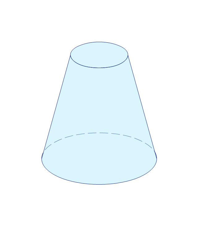
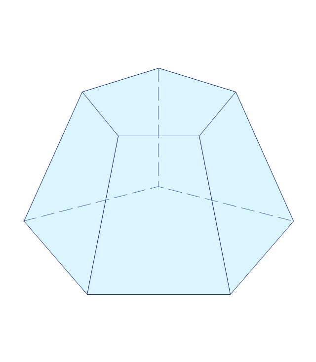
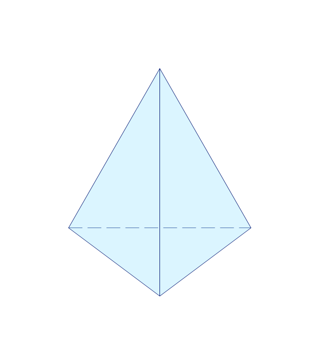
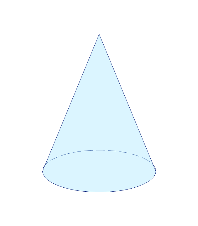
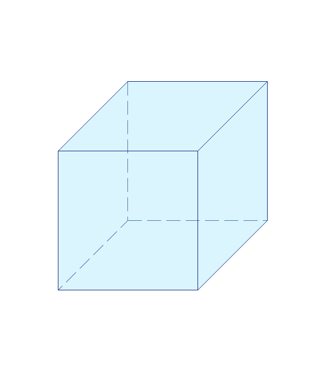
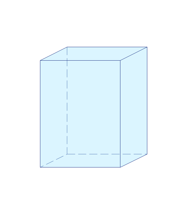
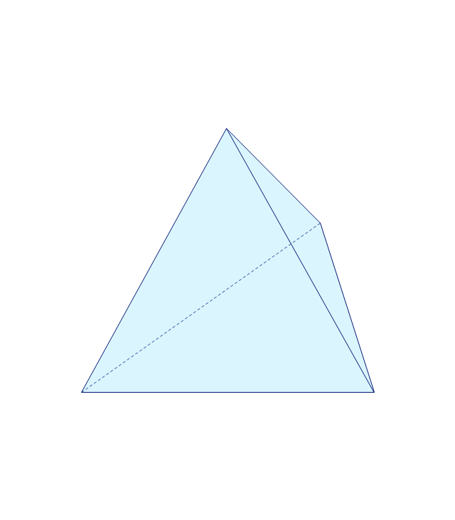
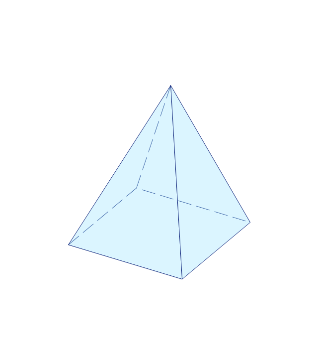
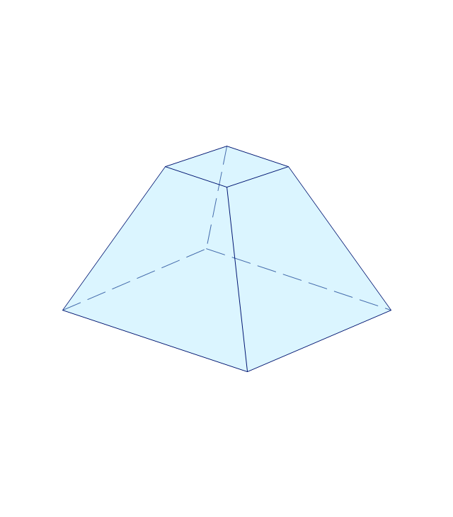
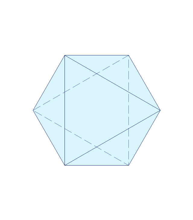
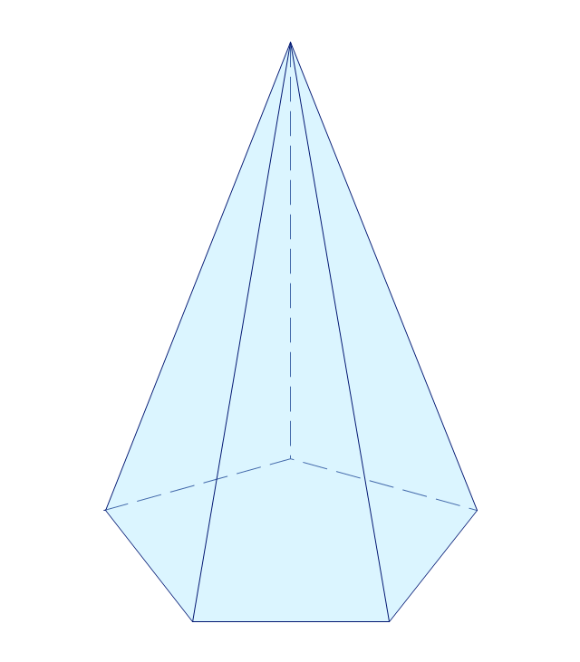
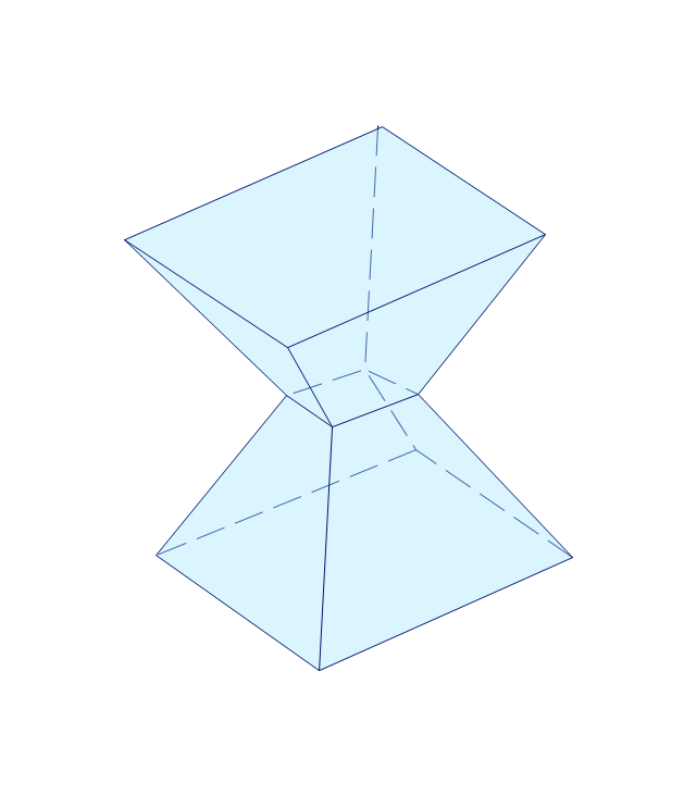
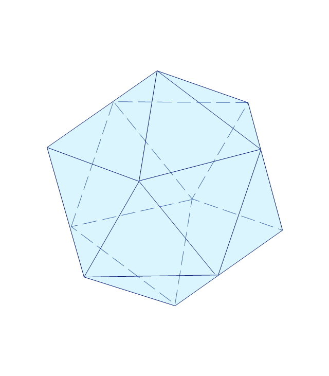
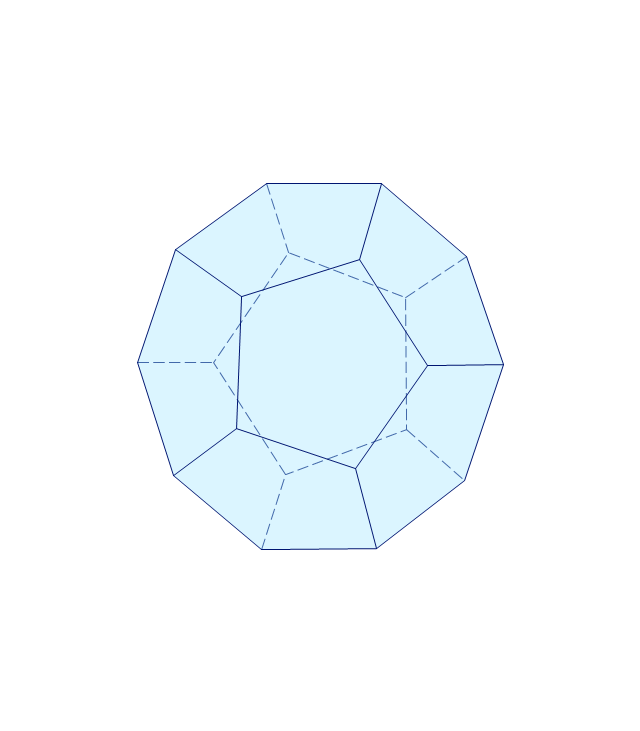
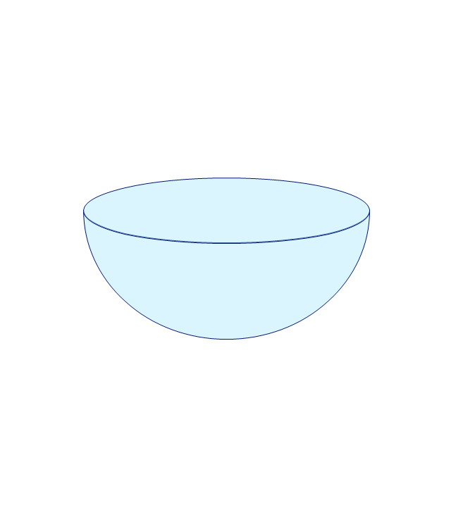
The vector stencils library "Solid geometry" contains 15 shapes of solid geometric figures.
Use these shapes to draw your geometrical diagrams and illustrations in the ConceptDraw PRO diagramming and vector drawing software extended with the Mathematics solution from the Science and Education area of ConceptDraw Solution Park.
Use these shapes to draw your geometrical diagrams and illustrations in the ConceptDraw PRO diagramming and vector drawing software extended with the Mathematics solution from the Science and Education area of ConceptDraw Solution Park.
Conical frustum
Pentagonal frustum
Tetrahedron
Cone
Cube
Rectangular cuboid
Regular tetrahedron
Square pyramid
Square frustum
Octahedron
Pentagonal pyramid
Irregular polyhedron
Icosahedron
Dodecahedron
Hemisphere
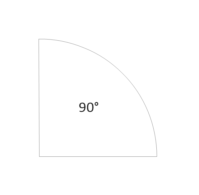
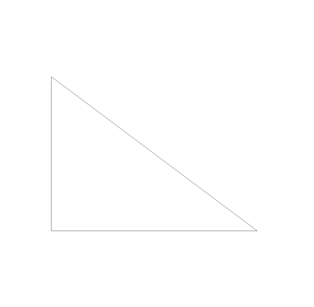
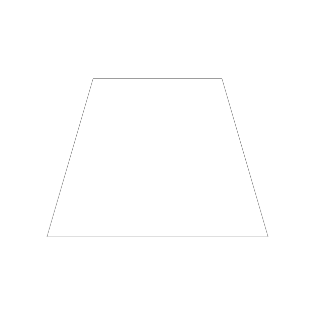
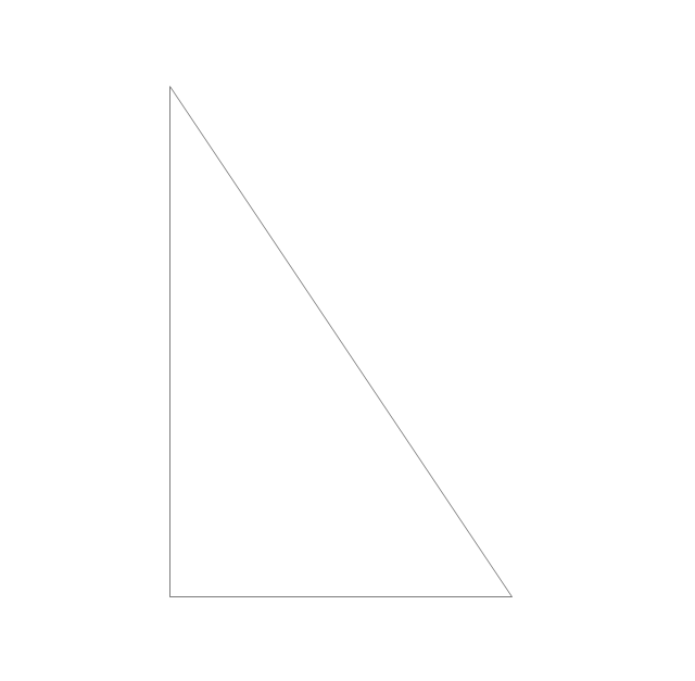
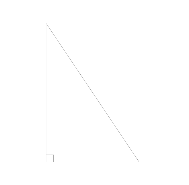
The vector stencils library "Plane geometry" contains 27 plane geometric figures.
Use these shapes to draw your geometrical diagrams and illustrations in the ConceptDraw PRO diagramming and vector drawing software extended with the Mathematics solution from the Science and Education area of ConceptDraw Solution Park.
Use these shapes to draw your geometrical diagrams and illustrations in the ConceptDraw PRO diagramming and vector drawing software extended with the Mathematics solution from the Science and Education area of ConceptDraw Solution Park.
Circular sector
Right triangle
Rectangle

Square

Pentagon

Isosceles trapezium
Parallelogram

Trapezium

Three-pointed star

Four-pointed star

Five-pointed star

Six-pointed star

Seven-pointed star

Eight-pointed star

Triangle

Equilateral triangle

Right triangle 2
Right triangle, angle box
Right triangle 3
Hexagon

Regular hexagon

Regular pentagon

Regular heptagon

Regular octagon

Rhombus

Circle

Ellipse

Developing Entity Relationship Diagrams
, crow's foot notation")
Most entity-relationship diagrams can be built with objects from Flowchart solution or ERD Solution which contains inbuilt templates. Follow these steps to create your own custom ERD diagram.
Don't be frightened if it looks complex, ConceptDraw PRO makes it easy to create an ERD, and hundreds of other diagrams, in minutes.
Ice Hockey Offside Diagram

Network Topology Mapper

Network Topology Mapper offers extensive drawing tools professional-looking network diagrams quickly and easily allowing you to clearly represent and communicate network architecture, topology, and design to engineers, stakeholders and end-users.
Ice Hockey Diagram — Defensive Strategy — Neutral Zone Trap

Scientific Symbols Chart

Mathematics Solution from the Science and Education area of ConceptDraw Solution Park includes a few shape libraries of plane, solid geometric figures, trigonometrical functions and greek letters to help you create different professional looking mathematic illustrations for science and education.
Ice Hockey Diagram – Penalty Kill Forecheck Angling Drill

UML Diagrams with ConceptDraw PRO

ConceptDraw PRO is a software that provides possibility of detailed UML diagrams. A large number of stencils that coresponds to UML diagram notation and task-oriented templates.
Basic Flowchart Symbols and Meaning


- Mathematics Symbols | Mathematical Diagrams | Scientific Symbols ...
- Mathematics Symbols | Design elements - Solid geometry ...
- Basic Diagrams Of Geometry With Names
- Mathematics Symbols | Mathematics | Mathematical Diagrams ...
- Basic Geometry Diagrams In Math
- Butt weld geometry | Buttwelding Diagrams
- Mathematics Symbols | Mathematical Diagrams | Scientific Symbols ...
- Mathematics Symbols | Mathematical Diagrams | Mathematics ...
- Geometry Diagrams
- Mathematical Diagrams | Mathematics | Butt weld geometry ...
- Tetrahedral Geometry Diagrams Using Solids
- Types Of Geometry Diagrams
- Geometry Diagram Maker
- How To Draw Figure In Geometry Fast Way To Solution
- Plane geometry - Vector stencils library | Mathematics Symbols ...
- Maths Project Geometry Diagrams
- Butt weld geometry | Welding symbols | Electrical Symbols, Electrical ...
- Example Of Geometry Shapes With Diagram
- Butt weld geometry | Mathematical Diagrams | Basic Flowchart ...
- Mathematics Symbols | Mathematical Diagrams | How to Draw ...
- ERD | Entity Relationship Diagrams, ERD Software for Mac and Win
- Flowchart | Basic Flowchart Symbols and Meaning
- Flowchart | Flowchart Design - Symbols, Shapes, Stencils and Icons
- Flowchart | Flow Chart Symbols
- Electrical | Electrical Drawing - Wiring and Circuits Schematics
- Flowchart | Common Flowchart Symbols
- Flowchart | Common Flowchart Symbols