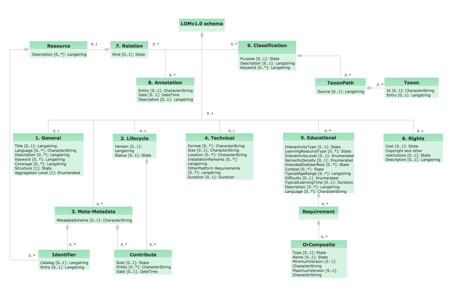
UML Class Diagram Generalization Example UML Diagrams

This sample describes the use of the classes, the generalization associations between them, the multiplicity of associations and constraints. Provided UML diagram is one of the examples set that are part of Rapid UML solution.
UML Class Diagram Constructor

The Rapid UML Solution for ConceptDraw DIAGRAM includes the UML Class Diagram library that helps you to design the UML Class Diagram quick and easy. You can simply and quickly drop the ready-to-use objects from the library into your document to create the UML Class Diagram.
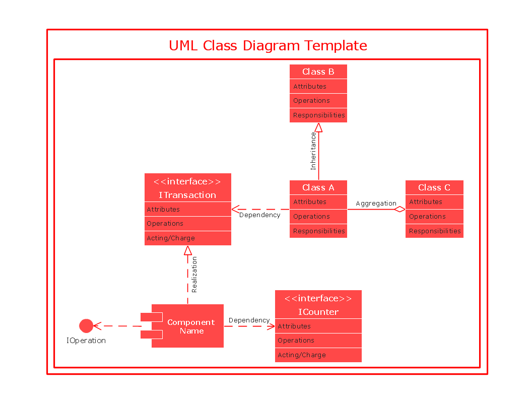
UML Class Diagram Notation

UML Class Diagram. Design Elements

UML Use Case Diagram. Design Elements


UML Class Diagram
UML Collaboration Diagram Example Illustration

This sample shows the creation process of the contact list and can be used at the staff training and staff working, at the attraction process the new clients.
UML Diagram Types List

UML Block Diagram

This sample shows the work of the taxi service and is used by taxi stations, by airports, in the tourism field and delivery service.
UML Class Diagrams. Diagramming Software for Design UML Diagrams

Use ConceptDraw DIAGRAM with UML class diagram templates, samples and stencil library from Rapid UML solution to show the classes of system, their attributes, operations or methods, and the relationships among the classes.
UML Notation

Two types of diagrams are used in UML: Structure Diagrams and Behavior Diagrams. Behavior Diagrams represent the processes proceeding in a modeled environment. Structure Diagrams represent the elements that compose the system.
Diagramming Software for designing UML Sequence Diagrams

UML Diagram Editor
About UML

This sample shows the work of the taxi service and is used by taxi stations, by airports, in the tourism field and delivery service.
UML Activity Diagram

Use ConceptDraw DIAGRAM diagramming and vector drawing software enhanced with Rapid UML solution from ConceptDraw Solution Park to create your own UML activity diagrams that show the business and operational workflows of components and overall flow of control in your systems. Such software provides coloring UML diagrams for various purposes and simplifying work of the engineers.
- Genralization And Inheritance In Uml Ppt
- Ppt On Generalization In Uml
- Uml Inheritance
- Generalization Vs Inheritance
- Uml Inheritance Example
- UML Class Diagram Constructor
- UML Class Diagram Notation | UML Class Diagram Generalization ...
- Uml Diagrams Using Tourism Management Application Pdf
- Uml Diagrams For Tourist With Pdf
- UML Class Diagram Generalization Example UML Diagrams | UML ...
- Uml Diagram Library Management Class Diagram In Visual Basic Pdf
- UML Class Diagram Generalization Example UML Diagrams | UML ...
- UML Class Diagram Generalization Example UML Diagrams ...
- UML Class Diagram Generalization Example UML Diagrams | UML ...
- UML Class Diagram Generalization Example UML Diagrams | UML ...
- Uml Class Diagram Templates Pdf
- Online Shopping Systems Uml Ppt
- UML Class Diagram Generalization Example UML Diagrams | UML ...
- UML Class Diagram Example - Apartment Plan | Stakeholder ...
- UML Class Diagram Generalization Example UML Diagrams | UML ...
- ERD | Entity Relationship Diagrams, ERD Software for Mac and Win
- Flowchart | Basic Flowchart Symbols and Meaning
- Flowchart | Flowchart Design - Symbols, Shapes, Stencils and Icons
- Flowchart | Flow Chart Symbols
- Electrical | Electrical Drawing - Wiring and Circuits Schematics
- Flowchart | Common Flowchart Symbols
- Flowchart | Common Flowchart Symbols