Process Flow Diagram Symbols

Process Flowchart


HelpDesk
How to Draw a Chemical Process Flow Diagram

Process Flow Diagrams
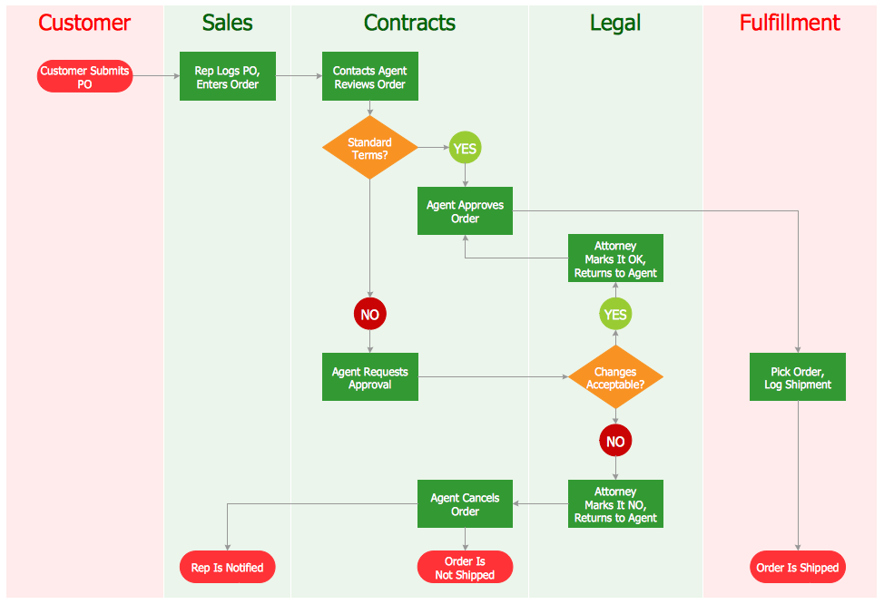
ConceptDraw DIAGRAM diagramming and vector drawing software extended with Flowcharts Solution from the "Diagrams" Area of ConceptDraw Solution Park offers the extensive drawing tools for quick and easy design professional looking Process Flow Diagrams.
"A process flow diagram (PFD) is a diagram commonly used in chemical and process engineering to indicate the general flow of plant processes and equipment. The PFD displays the relationship between major equipment of a plant facility and does not show minor details such as piping details and designations. Another commonly used term for a PFD is a flowsheet. ...
Process flow diagrams of multiple process units within a large industrial plant will usually contain less detail and may be called block flow diagrams or schematic flow diagrams." [Process flow diagram. Wikipedia]
The process flow diagram (PFD) template for the ConceptDraw PRO diagramming and vector drawing software is included in the Chemical and Process Engineering solution from the Engineering area of ConceptDraw Solution Park.
Process flow diagram (PFD) template
-template-process-flow-diagram-(pfd)-template.png--diagram-flowchart-example.png)
Types of Flowcharts


Accounting Flowchart: Purchasing, Receiving, Payable and Payment

Technical Flow Chart

Technical Flow Chart can be drawn by pencil on the paper, but it will be easier to use for designing a special software. ConceptDraw DIAGRAM diagramming and vector drawing software extended with Flowcharts Solution from the "Diagrams" Area of ConceptDraw Solution Park will be useful for this goal.
Flowchart Components

Process Flow Maps

- Types Of Flow Sheet In Chemical Engineering
- Chemical and Process Engineering | Cross Functional Flowchart ...
- Chemical Engineering Flowsheet Software
- Map Infographic Design | Pdf Types Of Flow Sheet In Chemical ...
- Uses Of Flow Sheet In Chemical Engineering
- Process Flowchart | Chemical Engineering Flowsheet Creator
- Chemical Engineering Process Flow Diagram Software Free
- Process Flowchart | Chemical and Process Engineering | Flow ...
- Chemical and Process Engineering | How to Draw a Chemical ...
- Chemical and Process Engineering | Top 5 Android Flow Chart ...
- ERD | Entity Relationship Diagrams, ERD Software for Mac and Win
- Flowchart | Basic Flowchart Symbols and Meaning
- Flowchart | Flowchart Design - Symbols, Shapes, Stencils and Icons
- Flowchart | Flow Chart Symbols
- Electrical | Electrical Drawing - Wiring and Circuits Schematics
- Flowchart | Common Flowchart Symbols
- Flowchart | Common Flowchart Symbols