Workflow Diagram
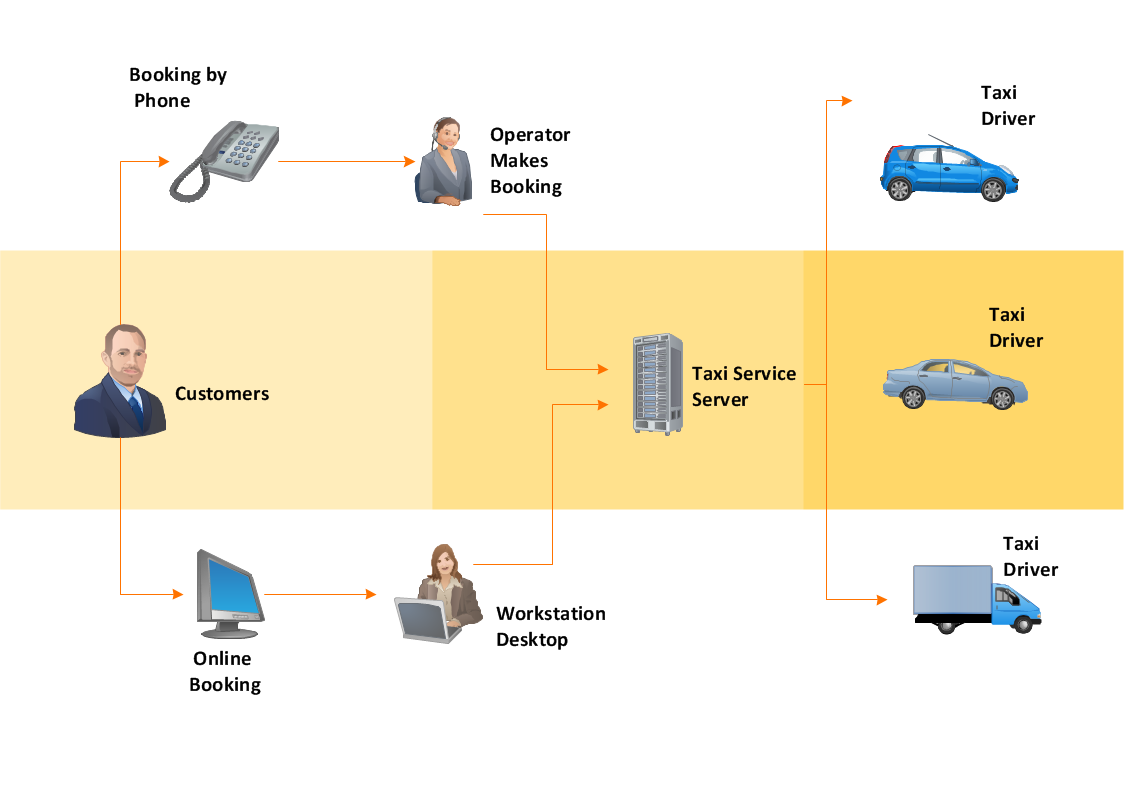
The workflow represents the transferring of data, documents or tasks during a work process. To make it easier to study and analyze working processes, and to present them in a simple visual manner, workflow diagrams are used. To create these diagrams professional use workflow diagram maker software ConceptDraw DIAGRAM.
Workflow Diagram Software
The best workflow diagram software you may find is ConceptDraw DIAGRAM. ConceptDraw DIAGRAM is world-known diagramming software that works for both Windows and Mac OS X platforms. The software contains complete set of features allows to draw diagrams faster. ConceptDraw DIAGRAM extended with the Workflow Diagram solution provides additional libraries, templates and samples for drawing professional workflow diagrams.
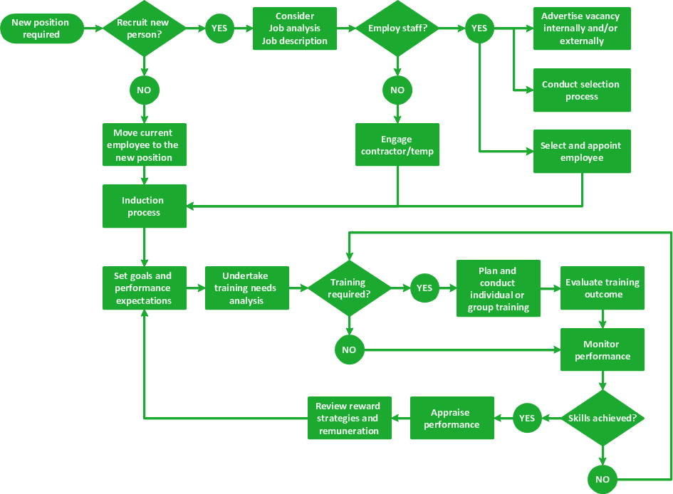
Process Flow Diagram

ConceptDraw DIAGRAM diagramming and vector drawing software extended with powerful tools of Flowcharts Solution from the "Diagrams" Area of ConceptDraw Solution Park is effective for drawing: Process Flow Diagram, Flow Process Diagram, Business Process Flow Diagrams.
TQM Software — Build Professional TQM Diagrams
IDEF3 Standard

UML Diagram Types List

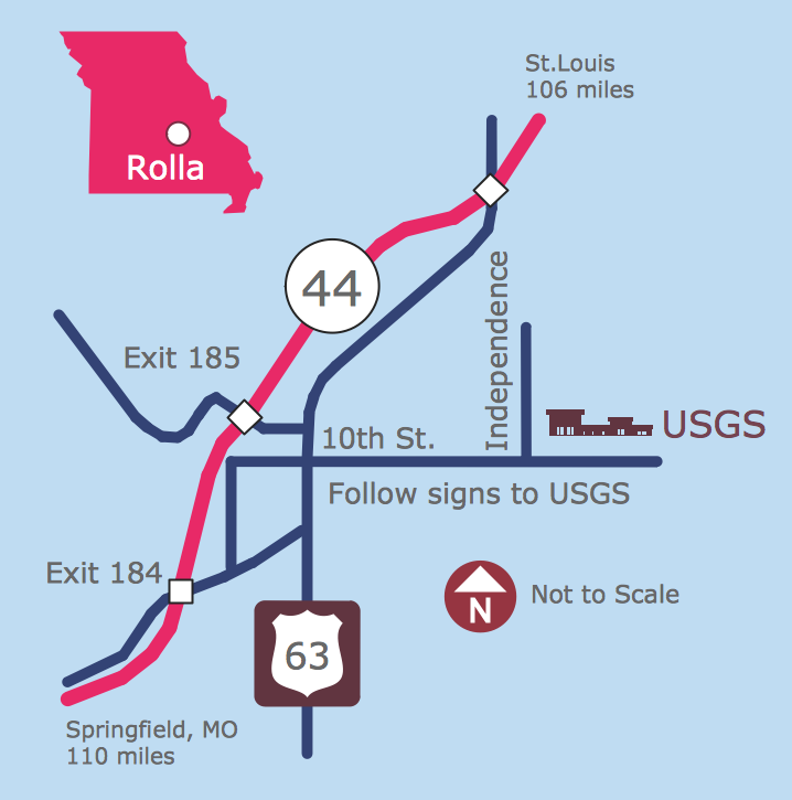
Maps and Directions
UML Deployment Diagram. Design Elements

ConceptDraw has 393 vector stencils in the 13 libraries that helps you to start using software for designing your own UML Diagrams. You can use the appropriate stencils of UML notation from UML Deployment library.
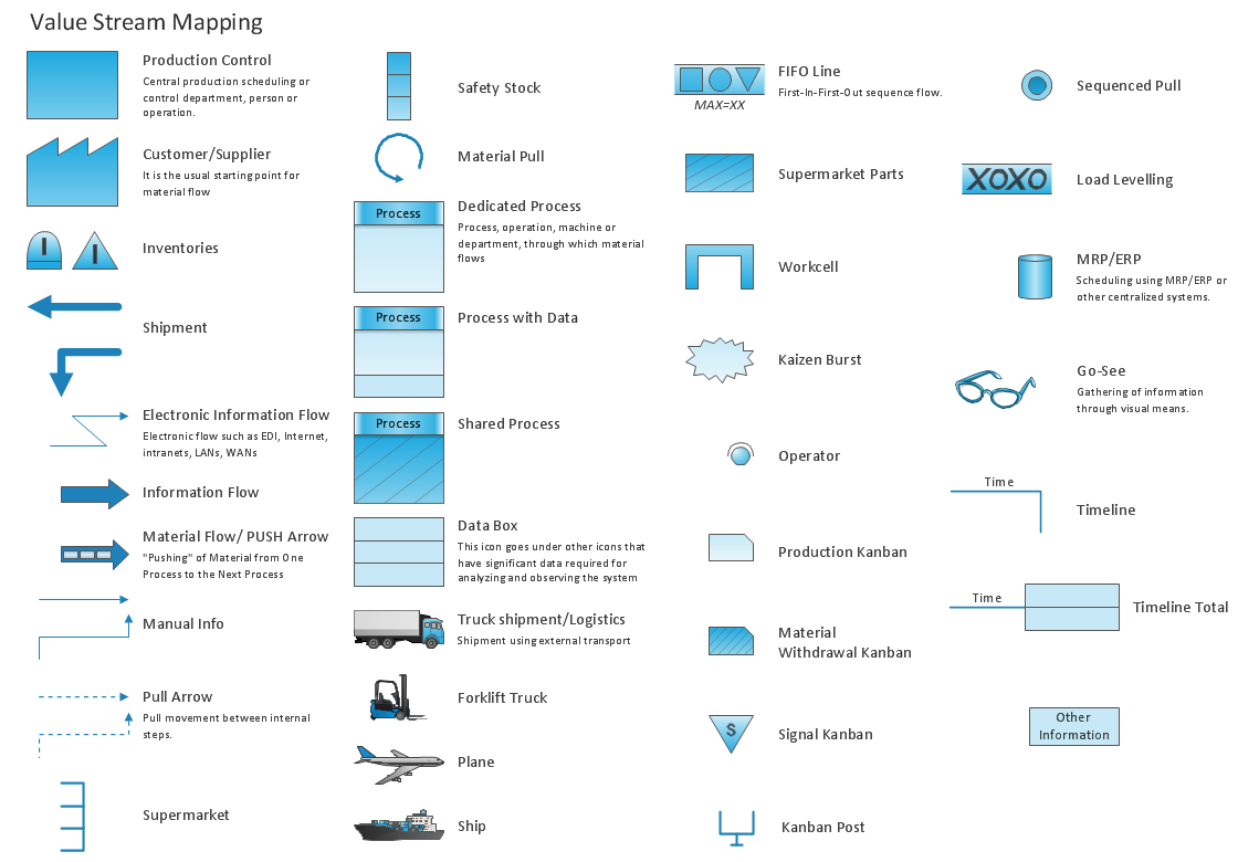
Value Stream Mapping Symbols
Circuits and Logic Diagram Software

Electrical Engineering solution helps you create quick and easy: Electrical schematics, Digital and analog logic designs, Circuit and wiring schematics and diagrams, Power systems diagrams, Maintenance and repair diagrams, Circuit board and amplifier diagrams, Integrated circuit schematics.
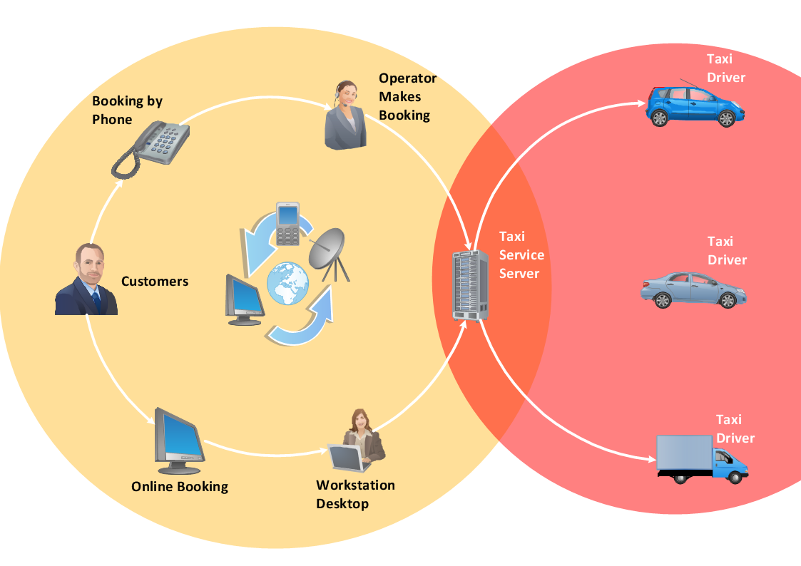
 Telecommunication Network Diagrams
Telecommunication Network Diagrams solution extends ConceptDraw DIAGRAM software with samples, templates, and great collection of vector stencils to help the specialists in a field of networks and telecommunications, as well as other users to create Computer systems networking and Telecommunication network diagrams for various fields, to organize the work of call centers, to design the GPRS networks and GPS navigational systems, mobile, satellite and hybrid communication networks, to construct the mobile TV networks and wireless broadband networks.
UML Class Diagram Notation

- Flow Chart Representating General Flow Of Work In Service Station
- Data Flow Diagram Service Station
- Service Station Flow Chart Drawing
- Flow Sheet Diagram Of An Oil Flow Station
- Process Flow Diagram | UML Deployment Diagram. Design ...
- Statlon Service Of Data Flow Diagram
- Dfd For Service Station
- Service Station Layout Diagram
- Diagram Layout Of Digital Service Station
- Process Flow Chart Of Trucking Service
- Basic Flowchart Symbols and Meaning | Flow Chart Symbols ...
- About UML | UML Diagram Types List | UML Class Diagram ...
- Process Flowchart | Basic Flowchart Symbols and Meaning | Types ...
- Functional Flow Block Diagram
- Data Flow Diagram
- Types of Flowchart - Overview | Process Flowchart | UML Use Case ...
- Replacing engine oil - Opportunity flowchart | Process flow diagram ...
- Block diagram - Gap model of service quality | Process Flowchart ...
- Process Flowchart | UML Block Diagram | Block diagram - Porter's ...
- Plant Layout Plans | Design elements - Stations | Electrical Drawing ...
- ERD | Entity Relationship Diagrams, ERD Software for Mac and Win
- Flowchart | Basic Flowchart Symbols and Meaning
- Flowchart | Flowchart Design - Symbols, Shapes, Stencils and Icons
- Flowchart | Flow Chart Symbols
- Electrical | Electrical Drawing - Wiring and Circuits Schematics
- Flowchart | Common Flowchart Symbols
- Flowchart | Common Flowchart Symbols