Electrical Symbols — Terminals and Connectors

26 libraries of the Electrical Engineering Solution of ConceptDraw DIAGRAM make your electrical diagramming simple, efficient, and effective. You can simply and quickly drop the ready-to-use objects from libraries into your document to create the electrical diagram.
Interior Design. Piping Plan — Design Elements

The vector stencils libraries "Pipes 1" and "Pipes 2" contain 28 and 48 pipe, tubing and fitting symbols, respectively.
"A fitting is used in pipe plumbing systems to connect straight pipe or tubing sections, to adapt to different sizes or shapes, and for other purposes, such as regulating or measuring fluid flow. The term plumbing is generally used to describe conveyance of water, gas, or liquid waste in ordinary domestic or commercial environments, whereas piping is often used to describe high-performance (e.g. high pressure, high flow, high temperature, hazardous materials) conveyance of fluids in specialized applications. The term tubing is sometimes used for lighter-weight piping, especially types that are flexible enough to be supplied in coiled form.
Fittings (especially uncommon types) require money, time, materials, and tools to install, so they are a non-trivial part of piping and plumbing systems." [Piping and plumbing fitting. Wikipedia]
Use the design elements libraries "Pipes 1" and "Pipes 2" for drawing plumbing and piping building plans, schematic diagrams, blueprints, or technical drawings of waste water disposal systems, hot and cold water supply systems using the ConceptDraw PRO diagramming and vector drawing software.
The shapes libraries "Pipes 1" and "Pipes 2" are contained in the Plumbing and Piping Plans solution from the Building Plans area of ConceptDraw Solution Park.
Piping symbols
.png--diagram-flowchart-example.png)
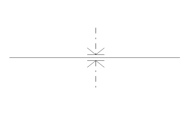
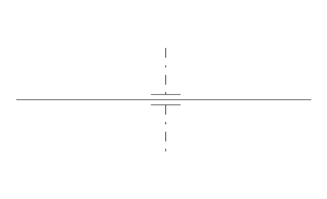
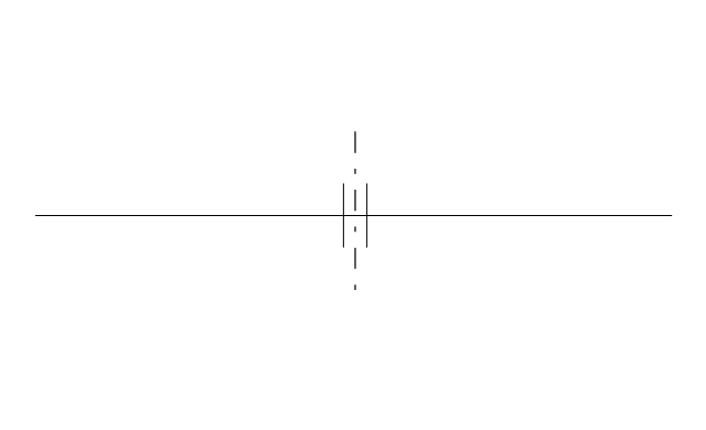
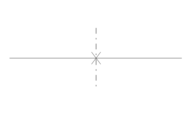
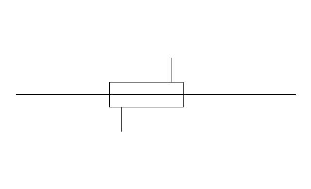
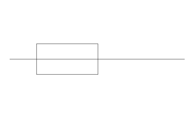
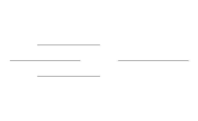
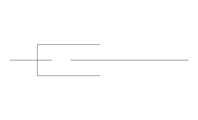
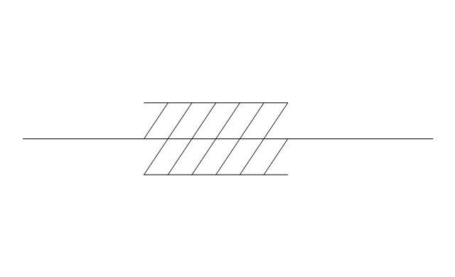
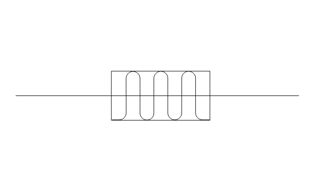
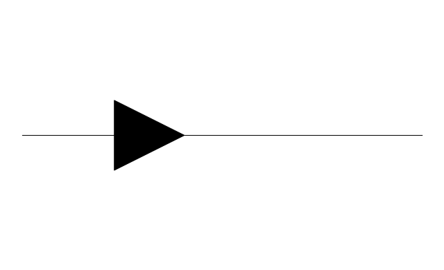
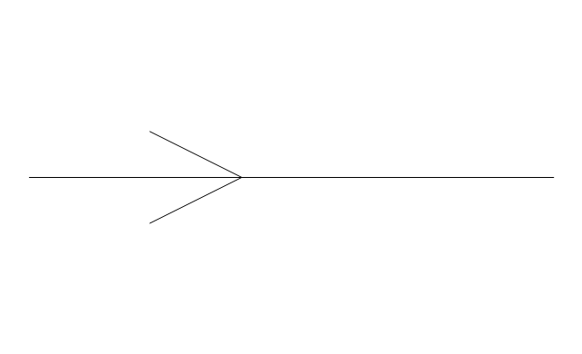
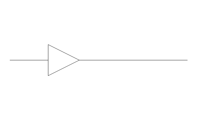
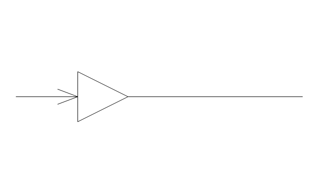
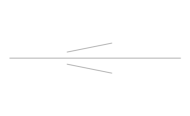
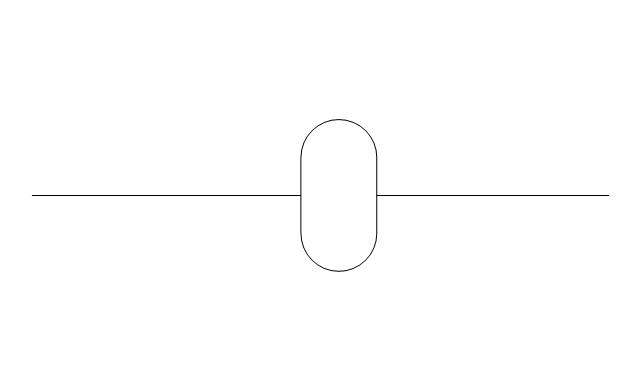
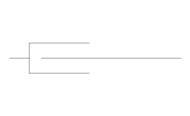
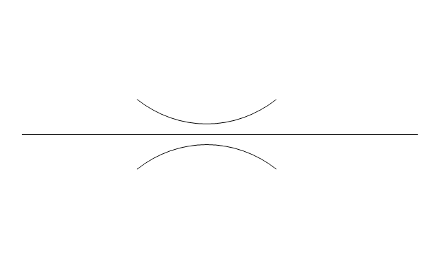
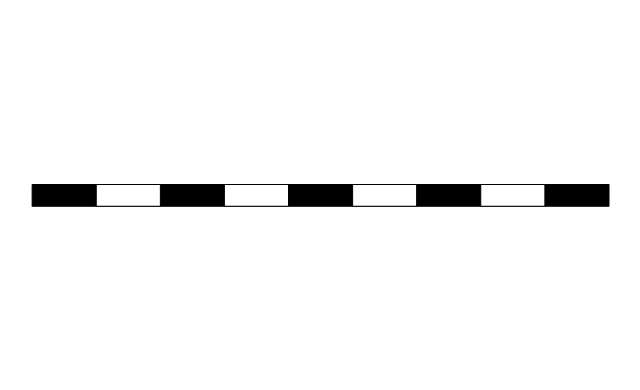
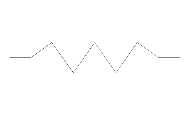
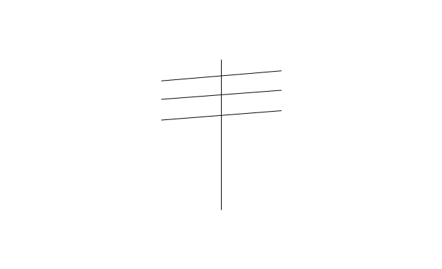
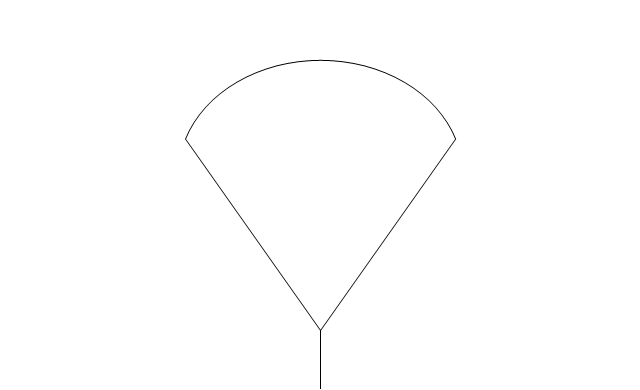
The vector stencils library "Terminals and connectors" contains 43 element symbols of terminals, connectors, plugs, polarized connectors, jacks, coaxial cables, and conductors.
Use it for drawing the wiring diagrams, electrical layouts, electronic schematics, and circuit diagrams.
"An electrical connector is an electro-mechanical device for joining electrical circuits as an interface using a mechanical assembly. Connectors consist of plugs (male-ended) and jacks (female-ended). The connection may be temporary, as for portable equipment, require a tool for assembly and removal, or serve as a permanent electrical joint between two wires or devices. An adapter can be used to effectively bring together dissimilar connectors.
There are hundreds of types of electrical connectors. Connectors may join two lengths of flexible copper wire or cable, or connect a wire or cable or optical interface to an electrical terminal.
In computing, an electrical connector can also be known as a physical interface... Cable glands, known as cable connectors in the US, connect wires to devices mechanically rather than electrically and are distinct from quick-disconnects performing the latter." [Electrical connector. Wikipedia]
"A terminal is the point at which a conductor from an electrical component, device or network comes to an end and provides a point of connection to external circuits. A terminal may simply be the end of a wire or it may be fitted with a connector or fastener. In network analysis, terminal means a point at which connections can be made to a network in theory and does not necessarily refer to any real physical object. In this context, especially in older documents, it is sometimes called a "pole".
The connection may be temporary, as seen in portable equipment, may require a tool for assembly and removal, or may be a permanent electrical joint between two wires or devices.
All electric cell have two terminals. The first is the positive terminal and the second is the negative terminal. The positive terminal looks like a metal cap and the negative terminal looks like a metal disc. The current flows from the positive terminal, and out through the negative terminal, replicative of current flow (positive (+) to negative (-) flow)." [Terminal (electronics). Wikipedia]
The shapes example "Design elements - Terminals and connectors" was drawn using the ConceptDraw PRO diagramming and vector drawing software extended with the Electrical Engineering solution from the Engineering area of ConceptDraw Solution Park.
Terminal and connector symbols

The vector stencils libraries "Pipes 1" and "Pipes 2" contain 28 and 48 pipe, tubing and fitting symbols, respectively.
"A fitting is used in pipe plumbing systems to connect straight pipe or tubing sections, to adapt to different sizes or shapes, and for other purposes, such as regulating or measuring fluid flow. The term plumbing is generally used to describe conveyance of water, gas, or liquid waste in ordinary domestic or commercial environments, whereas piping is often used to describe high-performance (e.g. high pressure, high flow, high temperature, hazardous materials) conveyance of fluids in specialized applications. The term tubing is sometimes used for lighter-weight piping, especially types that are flexible enough to be supplied in coiled form.
Fittings (especially uncommon types) require money, time, materials, and tools to install, so they are a non-trivial part of piping and plumbing systems." [Piping and plumbing fitting. Wikipedia]
Use the design elements libraries "Pipes 1" and "Pipes 2" for drawing plumbing and piping building plans, schematic diagrams, blueprints, or technical drawings of waste water disposal systems, hot and cold water supply systems using the ConceptDraw PRO diagramming and vector drawing software.
The shapes libraries "Pipes 1" and "Pipes 2" are contained in the Plumbing and Piping Plans solution from the Building Plans area of ConceptDraw Solution Park.
"A fitting is used in pipe plumbing systems to connect straight pipe or tubing sections, to adapt to different sizes or shapes, and for other purposes, such as regulating or measuring fluid flow. The term plumbing is generally used to describe conveyance of water, gas, or liquid waste in ordinary domestic or commercial environments, whereas piping is often used to describe high-performance (e.g. high pressure, high flow, high temperature, hazardous materials) conveyance of fluids in specialized applications. The term tubing is sometimes used for lighter-weight piping, especially types that are flexible enough to be supplied in coiled form.
Fittings (especially uncommon types) require money, time, materials, and tools to install, so they are a non-trivial part of piping and plumbing systems." [Piping and plumbing fitting. Wikipedia]
Use the design elements libraries "Pipes 1" and "Pipes 2" for drawing plumbing and piping building plans, schematic diagrams, blueprints, or technical drawings of waste water disposal systems, hot and cold water supply systems using the ConceptDraw PRO diagramming and vector drawing software.
The shapes libraries "Pipes 1" and "Pipes 2" are contained in the Plumbing and Piping Plans solution from the Building Plans area of ConceptDraw Solution Park.
Piping symbols
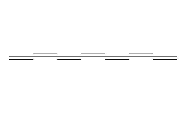
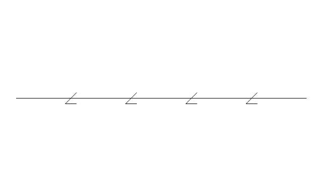
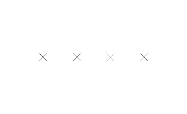
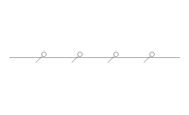
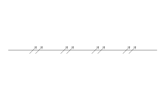
The vector stencils library "Pipes 2" contains 48 symbols of pipes. Use it for drawing plumbing and piping building plans, schematic diagrams, blueprints, or technical drawings of waste water disposal systems, hot and cold water supply systems in the ConceptDraw PRO diagramming and vector drawing software extended with the Plumbing and Piping Plans solution from the Building Plans area of ConceptDraw Solution Park.
Crossing
Junction
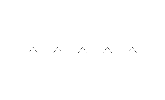
Basic support
Guide 1
Guide 2
Guide 3
Stopper
Anchor
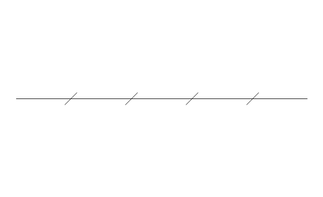
Support / anchor
Hunger
Cross
Double branch
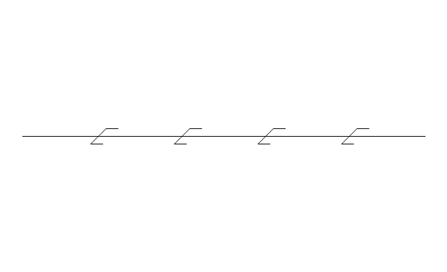
Jacketed
Sleeved
Sleeve joint
Expansion sleeve joint
Lagged
Bellows
Flow indication
Flow indication 2
Reducer
Reducer,arrow
Pipe bore change
Flexibility provision
Sleeve extension
Flow restrictor
Elbow 45
Elbow 90
Heated or cooled
Pneumatic line
Signal line
Electric line
Hydraulic line
Capillary line
Internal connection
Route radiation
Mechanical linkage
Electrical device
Vibratory device
Weight device
Spray device
Rotary motion
Stirring / fan
Access points
Trap
Expansion loop
Flexible hose
Flexible hose, flanged
The vector stencils library "Pipes 2" contains 48 symbols of pipes. Use it for drawing plumbing and piping building plans, schematic diagrams, blueprints, or technical drawings of waste water disposal systems, hot and cold water supply systems in the ConceptDraw PRO diagramming and vector drawing software extended with the Plumbing and Piping Plans solution from the Building Plans area of ConceptDraw Solution Park.
Crossing
Junction
Basic support
Guide 1
Guide 2
Guide 3
Stopper
Anchor
Support / anchor
Hunger
Cross
Double branch
Jacketed
Sleeved
Sleeve joint
Expansion sleeve joint
Lagged
Bellows
Flow indication
Flow indication 2
Reducer
Reducer,arrow
Pipe bore change
Flexibility provision
Sleeve extension
Flow restrictor
Elbow 45
Elbow 90
Heated or cooled
Pneumatic line
Signal line
Electric line
Hydraulic line
Capillary line
Internal connection
Route radiation
Mechanical linkage
Electrical device
Vibratory device
Weight device
Spray device
Rotary motion
Stirring / fan
Access points
Trap
Expansion loop
Flexible hose
Flexible hose, flanged
Audio Connectors

 Healthcare Management Workflow Diagrams
Healthcare Management Workflow Diagrams solution contains large set of colorful samples and libraries with predesigned vector pictograms and symbols of health, healthcare equipment, medical instruments, pharmaceutical tools, transport, medication, departments of healthcare organizations, the medical icons of people and human anatomy, as well as the predesigned flowchart objects, connectors and arrows, which make it the best for designing clear and comprehensive Medi?al Workflow Diagrams and Block Diagrams, Healthcare Management Flowcharts and Infographics, Healthcare Workflow Diagram, for depicting the healthcare workflow and clinical workflows in healthcare, for making the workflow analysis healthcare and healthcare workflow management.
- Expansion Joint Symbol
- Flexible Joint Symbol
- Electrical Symbol For Flexible Joint
- Flexible Conductor Symbol
- Symbol Of Pipe Joint
- Flexible Hose Fitting Drawing Symbol
- Circuit Symbols For Joint
- Hydraulic Joint Symbol
- Electrical Symbols , Electrical Diagram Symbols | Drow A Joint Of ...
- Symbol For Flanged Joint
- ERD | Entity Relationship Diagrams, ERD Software for Mac and Win
- Flowchart | Basic Flowchart Symbols and Meaning
- Flowchart | Flowchart Design - Symbols, Shapes, Stencils and Icons
- Flowchart | Flow Chart Symbols
- Electrical | Electrical Drawing - Wiring and Circuits Schematics
- Flowchart | Common Flowchart Symbols
- Flowchart | Common Flowchart Symbols