This IDEF3 diagram example was redesigned from the Wikimedia Commons file: 5-22 Final Object Schematic.jpg.
[commons.wikimedia.org/ wiki/ File:5-22_ Final_ Object_ Schematic.jpg]
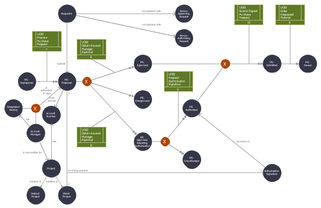
"Additional context-setting information is then added to the Transition Schematic as required. For example, the domain expert’s description indicated that purchase requests involving direct projects require an authorization signature. Additionally, the description included discussion of a constraint that account managers or their designated backups must approve all requests involving their projects. This information is noted directly on the schematic. The resulting Object Schematic is displayed in Figure 5-22." [IDEF3 Process Description Capture Method Report AL-TR-1995-XXXX. idef.com/ pdf/ Idef3_ fn.pdf]
The sample "Final object schematic - IDEF3 diagram" was created using the ConceptDraw PRO diagramming and vector drawing software extended with the solution "IDEF Business Process Diagrams" from the area "Business Processes" of ConceptDraw Solution Park.
[commons.wikimedia.org/ wiki/ File:5-22_ Final_ Object_ Schematic.jpg]
"Additional context-setting information is then added to the Transition Schematic as required. For example, the domain expert’s description indicated that purchase requests involving direct projects require an authorization signature. Additionally, the description included discussion of a constraint that account managers or their designated backups must approve all requests involving their projects. This information is noted directly on the schematic. The resulting Object Schematic is displayed in Figure 5-22." [IDEF3 Process Description Capture Method Report AL-TR-1995-XXXX. idef.com/ pdf/ Idef3_ fn.pdf]
The sample "Final object schematic - IDEF3 diagram" was created using the ConceptDraw PRO diagramming and vector drawing software extended with the solution "IDEF Business Process Diagrams" from the area "Business Processes" of ConceptDraw Solution Park.
IDEF3 business process diagram
This vector stencils library contains 47 SysML activity diagram symbols.
Use it to design your SysML activity diagrams using ConceptDraw PRO diagramming and vector drawing software.
"Activity diagrams are constructed from a limited number of shapes, connected with arrows. The most important shape types:
- rounded rectangles represent actions;
- diamonds represent decisions;
- bars represent the start (split) or end (join) of concurrent activities;
- a black circle represents the start (initial state) of the workflow;
- an encircled black circle represents the end (final state).
Arrows run from the start towards the end and represent the order in which activities happen." [Activity diagram. Wikipedia]
The vector stencils library "Activity diagram" is included in the SysML solution from the Software Development area of ConceptDraw Solution Park.
Action

Call behavior action

Accept event action

Accept time event action

Send signal action

Activity

Activity final node

Flow final node

Activity parameter node

Control operator node

Control operator - frame

Decision/Merge node

Fork/Join node

Initial node

isControl

isStream

isStream 2

isStream 3

Local precondition

Local postcondition

NoBuffer

Object node

Object node 2

Optional

Optional 2

OverWrite

Parameter set

Parameter set 2

Probability

Probability 2

Rate

Rate 2

Rate 3

Rate 4

Rate 5

Rate 6

Control flow

Control flow 2

Object flow

Object flow 2

Probability path

Rate path

In block definition diagram, activity, association

Activity partition

Activity partition - action

Interruptible activity region

Structured activity node

This vector stencils library contains 13 symbols for drawing UML interaction overview diagrams.
Interaction

Initial Node

Decision/Merge Node

Receive Signal Node

Fork/Join Node

Final Node

Lifeline
Message

Control Flow

Constraint

Parallel Control Flow

Smart Connector

Note

2014 FIFA World Cup

UML Activity Diagram. Design Elements
")

Business Processes

Wireframe Tools

Object-Oriented Design

UML State Machine Diagram.Design Elements

ConceptDraw has 393 vector stencils in the 13 libraries that helps you to start using software for designing your own UML Diagrams. You can use the appropriate stencils of UML notation from UML State Machine library.
Audit Steps

Value stream with ConceptDraw PRO

GUI Prototyping with ConceptDraw PRO

Quality visualization in your company

This arrow ring diagram sample was created on the base of the figure illustrating the webpage "Grant Life Cycle" from the Georgia College website. "Grant Life Cycle.
Define Opportunity: Funding opportunities can come from anywhere: databases, agency websites, professional publications or colleagues. GC subscribes to the database GRC. Federal grant opportunities can be found through Grants.gov.
Develop Proposal: Once an opportunity has been identified OGSP will do the following:
(1) Review the announcement for application requirements.
(2) Meet with the Principal Investigator (PI) to develop a project management plan.
(3) Work up a draft budget for PI approval.
(4) Complete the sponsor/ required forms and budget justification to be included in the application.
Submit & Negotiate: Applications can only be submitted by GC or the GC Foundation. Once internal approval has been received, designated staff in the appropriate office will submit the application on behalf of the PI and institution. If awarded, the GC or Foundation personnel will review and negotiate acceptable terms and conditions to GC, GC Fdn and/ or USG.
All of these are part of Pre-award services. ...
Award Setup: OGSP will review award documentation and assist all responsible parties with their roles and responsibilities during the grant. OGSP is available through the life of the award to provide support with any non-financial issues.
Manage Subawards: If subawards were identified at application, OGSP will issue the subaward using GC approved forms. If the need for a portion of the work to be completed by an outside entity is noted in the post-award phase, the Grants Compliance Manager will secure agency approval and then issue the subaward. OGSP will monitor the fiscal aspects of the subaward while the PI is responsible for the programmatic compliance.
Execute Project: OGSP continually monitors each grant for compliance with award terms & conditions. As legal representative, OGSP works with the PI and funder to expedite reports and resolve any issues that might arise.
Close Out Project: Once a grant has reached the end of the project period, all funders have requirements for final progress and financial reports. OGSP will work with the PI to make sure the progress report is submitted in a timely fashion and the Business & Finance completes the final invoices or report. The storage of the official project file is the responsibility of OGSP. All information and reports should be copied to the Grant Compliance Manager for inclusion in the official record." [gcsu.edu/ grants/ grantlifecycle.htm]
The arrow ring diagram example "Grant life cycle" was created using the ConceptDraw PRO diagramming and vector drawing software extended with the Target and Circular Diagrams solution from the Marketing area of ConceptDraw Solution Park.
www.conceptdraw.com/ solution-park/ marketing-target-and-circular-diagrams
Arrow ring diagram
Pyramid Diagram

- Final object schematic - IDEF3 diagram | Vector stencils library ...
- Final object schematic - IDEF3 diagram
- Contoh Flow Chart Final Projek
- Final Network Layout
- Flow Final
- Final State
- Vector stencils library - Activity diagram
- Final Node
- World Cup Final 2006 Pics
- Flow Chat For Final
- Vector stencils library - Activity diagram | UML interaction overview ...
- Project Design Final Presentation Uml Activity Diagram
- UML activity diagram - Alarm trigger processing | Vector stencils ...
- Final State Proffestional Diagram For Online Shopping
- UML activity diagram - Deposit slip processing | Vector stencils ...
- Warehouse Flowchart From Receiving An Order To Final Payment
- Final Product Of Business Process Mapping
- UML activity diagram - Cash withdrawal from ATM | UML Tool ...
- Design elements - UML interaction overview diagrams ...
- UML activity diagram (swimlanes) - Template | Design elements ...
- ERD | Entity Relationship Diagrams, ERD Software for Mac and Win
- Flowchart | Basic Flowchart Symbols and Meaning
- Flowchart | Flowchart Design - Symbols, Shapes, Stencils and Icons
- Flowchart | Flow Chart Symbols
- Electrical | Electrical Drawing - Wiring and Circuits Schematics
- Flowchart | Common Flowchart Symbols
- Flowchart | Common Flowchart Symbols