The vector stencils library "Toolbar control elements" contains 42 toolbar graphical control elements.
Use this toolbar control element UI icon set to design graphic user interface (GUI) of your software application for OS X 10.10 Yosemite Apple Mac operating system.
"A graphical control element or widget is an element of interaction in a graphical user interface (GUI), such as a button or a scroll bar. Controls are software components that a computer user interacts with through direct manipulation to read or edit information about an application. ...
Each widget facilitates a specific type of user-computer interaction, and appears as a visible part of the application's GUI as defined by the theme and rendered by the rendering engine. The theme makes all graphical control elements adhere to a unified aesthetic design and creates a sense of overall cohesion. Some widgets support interaction with the user, for example labels, buttons, and check boxes. Others act as containers that group the widgets added to them, for example windows, panels, and tabs." [Graphical control element. Wikipedia]
The icons example "Design elements - Toolbar control elements" was created using the ConceptDraw PRO diagramming and vector drawing software extended with the Mac OS User Interface solution from the Software Development area of ConceptDraw Solution Park.
Toolbar graphical control elements
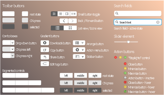
The vector stencils library "Toolbar control elements" contains 42 toolbar graphical control elements.
Use this tool bar control element UI icon set to design graphic user interface (GUI) of your software application for OS X 10.10 Yosemite Apple Mac operating system.
The example "Toolbar control elements - Vector stencils library" was created using the ConceptDraw PRO diagramming and vector drawing software extended with the Mac OS User Interface solution from the Software Development area of ConceptDraw Solution Park.
Drop-down button

Drop-down button - ON press left

Drop-down button - ON press right

Tool bar button

Tool bar button - ON press

Tool bar button - selected

Left segment

Left segment - ON press

Left segment - selected

Middle segment

Middle segment - ON press

Middle segment - selected

Right segment

Right segment - ON press

Right segment - selected

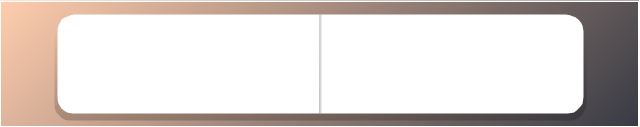
Segmented control - 2 buttons
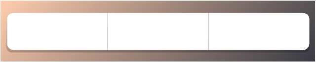
Segmented control - 3 buttons
Segmented control - 4 buttons

Small button toggle
Back - Forward button

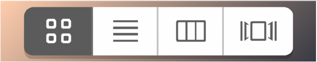
List/Icons view control
Arrange button

Action menu

Downloads button

Copy button

Share button

Edit tags button

Sidebar button

Slider element
Tool bar button 2

Tool bar button 2 - ON press

Tool bar button 2 - selected

Search field

Search field - active
"Stoplights" control
Close button

Minimize button

Maximize button

Close button - hover

Minimize button - hover

Maximize button - hover

Action button - inactive

The vector stencils library "Controls" contains 53 icons of Windows 8 controls.
Use it to design graphic user interface (GUI) prototypes of your software applications for Windows 8.
"A graphical control element or widget is an element of interaction in a graphical user interface (GUI), such as a button or a scroll bar. Controls are software components that a computer user interacts with through direct manipulation to read or edit information about an application. ...
Each widget facilitates a specific type of user-computer interaction, and appears as a visible part of the application's GUI as defined by the theme and rendered by the rendering engine. The theme makes all graphical control elements adhere to a unified aesthetic design and creates a sense of overall cohesion. Some widgets support interaction with the user, for example labels, buttons, and check boxes. Others act as containers that group the widgets added to them, for example windows, panels, and tabs." [Graphical control element. Wikipedia]
The design elements example "Controls - Vector stencils library" was created using the ConceptDraw PRO diagramming and vector drawing software extended with the Windows 8 User Interface solution from the Software Development area of ConceptDraw Solution Park.
Balloon

Check box - checked
Check box - unchecked
Radio button - selected

Radio button

Group box
Standard command button
Default command button
Link

Command link - selected
Command link

Command link
Command link 2
Drop-down button with text box
Drop-down button with text box - selected
Drop-down list
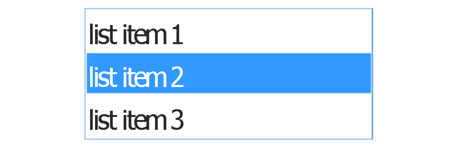
List item

List item - selected

Drop-down button with text box 2
Drop-down list 2
Drop-down button
Drop-down button - selected
Combo box
Combo box 2
Combo box with scroller
List box
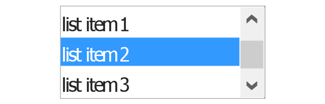
List box with scrollbar
List view
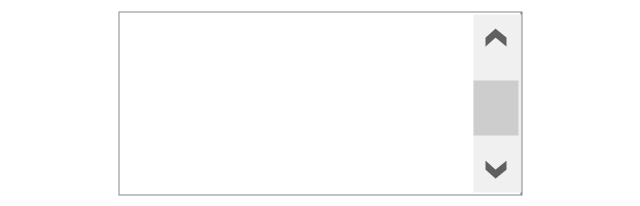
Vertical scroller

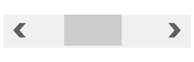
Horizontal scroller
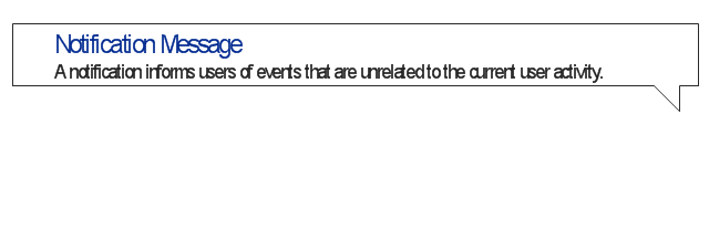
Notification
Options button

Close button

Text label

Progress bar
Search box

Search symbol

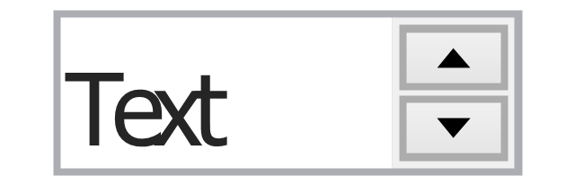
Spin control
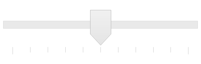
Slider - 5 intervals
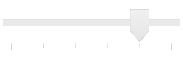
Slider - 10 intervals
Status bar

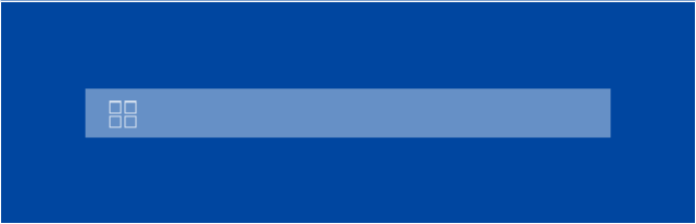
Start button

Status bar with Start button
Viewed window

Current window state

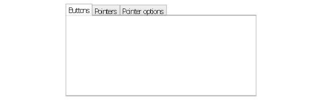
Tab control

Tab control - selected

Tab view page

Tab view
Text box
Text box label
Tooltip

Infotip
Business Process Elements: Activities
")

The vector stencils library "HVAC controls" contains 23 symbols of HVAC controls (sensors, actuators, timers, controllers, I/ O points).
"HVAC (... Heating, Ventilation and Air Conditioning) is a control system that applies regulation to a heating and/ or air conditioning system. ...
Central controllers and most terminal unit controllers are programmable, meaning the direct digital control program code may be customized for the intended use. The program features include time schedules, setpoints, controllers, logic, timers, trend logs, and alarms. The unit controllers typically have analog and digital inputs that allow measurement of the variable (temperature, humidity, or pressure) and analog and digital outputs for control of the transport medium (hot/ cold water and/ or steam). Digital inputs are typically (dry) contacts from a control device, and analog inputs are typically a voltage or current measurement from a variable (temperature, humidity, velocity, or pressure) sensing device. Digital outputs are typically relay contacts used to start and stop equipment, and analog outputs are typically voltage or current signals to control the movement of the medium (air/ water/ steam) control devices such as valves, dampers, and motors." [HVAC control system. Wikipedia]
Use the design elements library "HVAC controls" for drawing the HVAC system diagrams, controls drawings, and automated building control and environmental control system layuout floor plans using the ConceptDraw PRO diagramming and vector drawing software.
The shapes library "HVAC controls" is included in the HVAC Plans solution from the Building Plans area of ConceptDraw Solution Park.
HVAC control symbols

"HVAC (stands for Heating, Ventilation and Air Conditioning) is a control system that applies regulation to a heating and/ or air conditioning system. Usually a sensing device is used to compare the actual state (e.g., temperature) with a target state. Then the control system draws a conclusion what action has to be taken (e.g., start the blower).
More complex HVAC systems can interface to Building Automation System (BAS) to allow the building owners to have more control over the heating or cooling units. The building owner can monitor the system and respond to alarms generated by the system from local or remote locations." [HVAC control system. Wikipedia]
The vector stencils library "HVAC control equipment" contains 48 symbols of heating, ventilation, air conditioning, refrigeration and automated building control equipment.
Use the design elements library HVAC control equipment to draw HVAC plans, schematic diagrams of heating, ventilation, air conditioning, refrigeration and automated building control systems, environmental control design building plans and equipment layouts using the ConceptDraw PRO diagramming and vector drawing software.
The shapes library HVAC control equipment is contained in the HVAC Plans solution from the Building Plans area of ConceptDraw Solution Park.
HVAC control equipment symbols

Basic Flowchart Symbols and Meaning


The vector stencils library "Instruments" contains 72 symbols of control instruments and measuring devices: meters and gauges, and callouts, text boxes, and inserts.
Use these shapes to create annotated process flow diagrams (PFD), flow control, manufacturing processes, and distribution system diagrams.
"Process control is an engineering discipline that deals with architectures, mechanisms and algorithms for maintaining the output of a specific process within a desired range.
Process control is extensively used in industry and enables mass production of continuous processes such as oil refining, paper manufacturing, chemicals, power plants and many other industries. Process control enables automation, with which a small staff of operating personnel can operate a complex process from a central control room." [Process control. Wikipedia]
The example "Design elements - Instruments" was created using the ConceptDraw PRO diagramming and vector drawing software extended with the Chemical and Process Engineering solution from the Engineering area of ConceptDraw Solution Park.
Process control instrument symbols

The vector stencils library "Switches" contains 25 symbols of electrical and light switches and breakers.
"In electrical engineering, a switch is an electrical component that can break an electrical circuit, interrupting the current or diverting it from one conductor to another.
The most familiar form of switch is a manually operated electromechanical device with one or more sets of electrical contacts, which are connected to external circuits.
A switch may be directly manipulated by a human as a control signal to a system, ... or to control power flow in a circuit, such as a light switch. Automatically operated switches can be used to control the motions of machines, for example, to indicate that a garage door has reached its full open position or that a machine tool is in a position to accept another workpiece. Switches may be operated by process variables such as pressure, temperature, flow, current, voltage, and force, acting as sensors in a process and used to automatically control a system. For example, a thermostat is a temperature-operated switch used to control a heating process. A switch that is operated by another electrical circuit is called a relay." [Switch. Wikipedia]
Use the design elements library "Switches" for drawing light switches layouts, electrical and telecommunication equipment floor plans for building design and construction using the ConceptDraw PRO diagramming and vector drawing software.
The shapes library "Switches" is included in the Electric and Telecom Plans solution from the Building Plans area of ConceptDraw Solution Park.
Electrical switch symbols

The vector stencils library "Telecom" contains 20 telecommunication icons. Use it to design your IT and telecom illustrations and infographics with ConceptDraw PRO diagramming and vector drawing software.
"Telecommunication is the transmission of signs, signals, writings, images and sounds or intelligence of any nature by wire, radio, optical or other electromagnetic systems, as defined by the International Telecommunication Union (ITU).
Telecommunication occurs when the exchange of information between communication participants includes the use of technology. It is transmitted either electrically over physical media, such as cables, or via electromagnetic radiation. Such transmission paths are often divided into communication channels which afford the advantages of multiplexing. ...
Modern technologies for long-distance communication usually involve electrical and electromagnetic technologies, such as telegraph, telephone, and teleprinter, networks, radio, microwave transmission, fiber optics, and communications satellites." [Telecommunication. Wikipedia]
The telecommunication icon set example "Design elements - Telecom" is included in the Computers and Communications solution from the Illustration area of ConceptDraw Solution Park.
Telecommunication icon set
The vector stencils library "Progressive disclosure controls" contains 12 icons of Windows 8 progressive disclosure controls.
Use it to design graphic user interface (GUI) prototypes of your software applications for Windows 8.
The icons example "Design elements - Progressive disclosure controls" was created using the ConceptDraw PRO diagramming and vector drawing software extended with the Windows 8 User Interface solution from the Software Development area of ConceptDraw Solution Park.
UI icons
The vector stencils library "Valves and fittings" contains 104 symbols of valve components.
Use these icons for drawing industrial piping systems; process, vacuum, and fluids piping; hydraulics piping; air and gas piping; materials distribution; and liquid transfer systems.
"A valve is a device that regulates, directs or controls the flow of a fluid (gases, liquids, fluidized solids, or slurries) by opening, closing, or partially obstructing various passageways. Valves are technically valves fittings, but are usually discussed as a separate category. In an open valve, fluid flows in a direction from higher pressure to lower pressure.
The simplest, and very ancient, valve is simply a freely hinged flap which drops to obstruct fluid (gas or liquid) flow in one direction, but is pushed open by flow in the opposite direction. This is called a check valve, as it prevents or "checks" the flow in one direction. ...
Valves are found in virtually every industrial process, including water & sewage processing, mining, power generation, processing of oil, gas & petroleum, food manufacturing, chemical & plastic manufacturing and many other fields. ...
Valves may be operated manually, either by a handle, lever, pedal or wheel. Valves may also be automatic, driven by changes in pressure, temperature, or flow. These changes may act upon a diaphragm or a piston which in turn activates the valve, examples of this type of valve found commonly are safety valves fitted to hot water systems or boilers.
More complex control systems using valves requiring automatic control based on an external input (i.e., regulating flow through a pipe to a changing set point) require an actuator. An actuator will stroke the valve depending on its input and set-up, allowing the valve to be positioned accurately, and allowing control over a variety of requirements." [Valve. Wikipedia]
The example "Design elements - Valves and fittings" was created using the ConceptDraw PRO diagramming and vector drawing software extended with the Chemical and Process Engineering solution from the Engineering area of ConceptDraw Solution Park.
Valves and fittings symbols

The vector stencils library "Switches and relays" contains 58 symbols of electrical contacts, switches, relays, circuit breakers, selectors, connectors, disconnect devices, switching circuits, current regulators, and thermostats for electrical devices.
"In electrical engineering, a switch is an electrical component that can break an electrical circuit, interrupting the current or diverting it from one conductor to another.
The most familiar form of switch is a manually operated electromechanical device with one or more sets of electrical contacts, which are connected to external circuits. Each set of contacts can be in one of two states: either "closed" meaning the contacts are touching and electricity can flow between them, or "open", meaning the contacts are separated and the switch is nonconducting. The mechanism actuating the transition between these two states (open or closed) can be either a "toggle" (flip switch for continuous "on" or "off") or "momentary" (push-for "on" or push-for "off") type.
A switch may be directly manipulated by a human as a control signal to a system, such as a computer keyboard button, or to control power flow in a circuit, such as a light switch. Automatically operated switches can be used to control the motions of machines, for example, to indicate that a garage door has reached its full open position or that a machine tool is in a position to accept another workpiece. Switches may be operated by process variables such as pressure, temperature, flow, current, voltage, and force, acting as sensors in a process and used to automatically control a system. ... A switch that is operated by another electrical circuit is called a relay. Large switches may be remotely operated by a motor drive mechanism. Some switches are used to isolate electric power from a system, providing a visible point of isolation that can be padlocked if necessary to prevent accidental operation of a machine during maintenance, or to prevent electric shock." [Switch. Wikipedia]
"A relay is an electrically operated switch. Many relays use an electromagnet to mechanically operate a switch, but other operating principles are also used, such as solid-state relays. Relays are used where it is necessary to control a circuit by a low-power signal (with complete electrical isolation between control and controlled circuits), or where several circuits must be controlled by one signal. The first relays were used in long distance telegraph circuits as amplifiers: they repeated the signal coming in from one circuit and re-transmitted it on another circuit. Relays were used extensively in telephone exchanges and early computers to perform logical operations.
A type of relay that can handle the high power required to directly control an electric motor or other loads is called a contactor. Solid-state relays control power circuits with no moving parts, instead using a semiconductor device to perform switching. Relays with calibrated operating characteristics and sometimes multiple operating coils are used to protect electrical circuits from overload or faults; in modern electric power systems these functions are performed by digital instruments still called "protective relays"." [Relay. Wikipedia]
The shapes example "Design elements - Switches and relays" was drawn using the ConceptDraw PRO diagramming and vector drawing software extended with the Electrical Engineering solution from the Engineering area of ConceptDraw Solution Park.
Switch and relay symbols

Quality Control Chart Software — ISO Flowcharting

The quality control chart is a graphic that illustrates the accordance of processes or products to the intended specifications and degree of differences from them. Depending on what type of data you need analyze, there are used different types of quality control charts: X-bar charts, S charts, Np charts.
- HVAC Plans | Block diagram - Automotive HVAC system | Design ...
- Design elements - Toolbar and Navigation Bar Buttons | Toolbar ...
- Toolbar control elements - Vector stencils library | Design elements ...
- Design elements - HVAC control equipment | Block diagram ...
- Design elements - HVAC control equipment
- HVAC Business Plan | HVAC Marketing Plan | Design elements ...
- Design elements - HVAC control equipment | Basic Flowchart ...
- Design elements - HVAC controls | HVAC controls - Vector stencils ...
- Example Of Element
- Personal area (PAN) networks. Computer and Network Examples ...
- IDEF0 diagram - Inter-box connections | Controls - Vector stencils ...
- Design elements - HVAC control equipment | HVAC control ...
- Design elements - HVAC control equipment | HVAC Plans | Design ...
- Design elements - Alarm and access control | Design elements ...
- Design elements - HVAC control equipment | How To use House ...
- Design elements - Aircraft | Fishbone Diagram | Design elements ...
- Design elements - HVAC equipment
- Design elements - HVAC ductwork | Interior Design Registers, Drills ...
- Design elements - HVAC controls
- Design elements - HVAC controls | Design elements - HVAC control ...
- ERD | Entity Relationship Diagrams, ERD Software for Mac and Win
- Flowchart | Basic Flowchart Symbols and Meaning
- Flowchart | Flowchart Design - Symbols, Shapes, Stencils and Icons
- Flowchart | Flow Chart Symbols
- Electrical | Electrical Drawing - Wiring and Circuits Schematics
- Flowchart | Common Flowchart Symbols
- Flowchart | Common Flowchart Symbols