Bubble diagrams in Landscape Design with ConceptDraw DIAGRAM

This sport field plan sample was designed on the base of the Wikipedia file: VolleyballCourt.svg. [en.wikipedia.org/ wiki/ File:VolleyballCourt.svg]
This file is licensed under the Creative Commons Attribution-Share Alike 3.0 Unported license. [creativecommons.org/ licenses/ by-sa/ 3.0/ deed.en]
"Volleyball is a team sport in which two teams of six players are separated by a net. Each team tries to score points by grounding a ball on the other team's court under organized rules. It has been a part of the official program of the Summer Olympic Games since 1964. ...
The court dimensions.
A volleyball court is 18 m (59 ft) long and 9 m (29.5 ft) wide, divided into 9 m × 9 m halves by a one-meter (40-inch) wide net. The top of the net is 2.43 m (8 ft 0 in) above the center of the court for men's competition, and 2.24 m (7 ft 4 in) for women's competition, varied for veterans and junior competitions.
The minimum height clearance for indoor volleyball courts is 7 m (23 ft), although a clearance of 8 m (26 ft) is recommended.
A line 3 m (9.84 ft) from and parallel to the net is considered the "attack line". This "3 meter" (or "10-foot") line divides the court into "back row" and "front row" areas (also back court and front court). These are in turn divided into 3 areas each: these are numbered as follows, starting from area "1", which is the position of the serving player.
After a team gains the serve (also known as siding out), its members must rotate in a clockwise direction, with the player previously in area "2" moving to area "1" and so on, with the player from area "1" moving to area "6".
The team courts are surrounded by an area called the free zone which is a minimum of 3 meters wide and which the players may enter and play within after the service of the ball. All lines denoting the boundaries of the team court and the attack zone are drawn or painted within the dimensions of the area and are therefore a part of the court or zone. If a ball comes in contact with the line, the ball is considered to be "in". An antenna is placed on each side of the net perpendicular to the sideline and is a vertical extension of the side boundary of the court. A ball passing over the net must pass completely between the antennae (or their theoretical extensions to the ceiling) without contacting them." [Volleyball. Wikipedia]
The sport field plan example "Volleyball court dimensions" was created using the ConceptDraw PRO diagramming and vector drawing software extended with the Sport Field Plans solution from the Building Plans area of ConceptDraw Solution Park.
Sport field plan

This office interior design sample illustrates cubicle layout of furniture on the floor plan.
"Тhe cubicle, cubicle desk, office cubicle or cubicle workstation is a partially enclosed workspace, separated from neighboring workspaces by partitions that are usually 5–6 feet (1.5–1.8 m) tall. Its purpose is to isolate office workers from the sights and noises of an open workspace so that they may concentrate without distractions. Cubicles are composed of modular elements such as work surfaces, overhead bins, drawers, and shelving, which can be configured depending on the user's needs. Installation is generally performed by professionals, although some cubicles allow configuration changes to be performed by users without specific training." [Cubicle. Wikipedia]
The office interior design example "Cubicle layout" was created using the ConceptDraw DIAGRAM diagramming and vector drawing software extended with the Office Layout Plans solution from the Building Plans area of ConceptDraw Solution Park.
Office floor plan

 Seven Management and Planning Tools
Seven Management and Planning Tools solution extends ConceptDraw DIAGRAM and ConceptDraw MINDMAP with features, templates, samples and libraries of vector stencils for drawing management mind maps and diagrams.
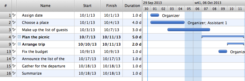
Managing the task list
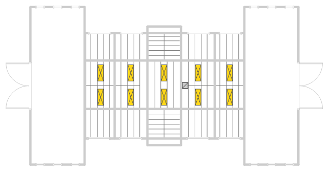
This reflected ceiling plan sample was created on the base of the RCP from the website of the University of Idaho.
"We tried a number of skylight layouts and decided to use a plan with five 2' by 6' skylights on each side of the gable roof at 18' above the floor. ... Reflected ceiling plan showing proposed skylights framed between roof rafters. The rafters are 2'9" apart only allowing for 2' wide skylights." [webpages.uidaho.edu/ arch571/ AASouth4.htm]
The skylights layout example "Studio space RCP" was created using the ConceptDraw DIAGRAM diagramming and vector drawing software extended with the Reflected Ceiling Plans solution from the Building Plans area of ConceptDraw Solution Park.
Reflected ceiling plan
 Histograms
How to make a Histogram? Making a Histogram is an incredibly easy process when it is done with ConceptDraw DIAGRAM. The Histograms Solution enhances ConceptDraw DIAGRAM functionality with extensive drawing tools, numerous samples, and examples; also a quick-start template and library of ready vector stencils for visualization the data and professional drawing Histograms.
HelpDesk
How to Draw a Histogram

 Seven Management and Planning Tools
Seven Management and Planning Tools solution extends ConceptDraw DIAGRAM and ConceptDraw MINDMAP with features, templates, samples and libraries of vector stencils for drawing management mind maps and diagrams.
- Network Layout Floor Plans | Network Layout | Design elements ...
- Office plan - Cubicle layout | Office furniture - Vector stencils library ...
- Fire Exit Plan . Building Plan Examples | How To Draw Building ...
- Interior Design Office Layout Plan Design Element | Building ...
- UML Class Diagram Example - Apartment Plan | Create Floor Plans ...
- UML Class Diagram Example - Buildings and Rooms | Room ...
- Layout And Side Plan
- Office plan - Cubicle layout | Office Layout Plans | Building Drawing ...
- Floor Plans | How To use House Electrical Plan Software | How To ...
- Network Layout Floor Plans | Ethernet local area network layout floor ...
- Floor Plan Vector
- Interior Design Office Layout Plan Design Element | Seating Plans ...
- How To use Kitchen Design Software | Kitchen Planning Software ...
- How To use Appliances Symbols for Building Plan | How To use ...
- Interior Design Office Layout Plan Design Element | Building ...
- Reflected Ceiling Plans | How to Create a Reflected Ceiling Floor ...
- Interior Design Office Layout Plan Design Element | Design ...
- Kitchen Plan Symbol
- How To use Appliances Symbols for Building Plan | How To use ...
- Comparison sport playing areas | Sport Field Plans | Playground ...
- ERD | Entity Relationship Diagrams, ERD Software for Mac and Win
- Flowchart | Basic Flowchart Symbols and Meaning
- Flowchart | Flowchart Design - Symbols, Shapes, Stencils and Icons
- Flowchart | Flow Chart Symbols
- Electrical | Electrical Drawing - Wiring and Circuits Schematics
- Flowchart | Common Flowchart Symbols
- Flowchart | Common Flowchart Symbols