Electrical and Telecom Plan Software
ConceptDraw is a fast way to draw: Electrical circuit diagrams, Electrical wiring diagrams, Telecom plans, Schematics, House electrical plans, Control wiring diagrams, Power-riser diagrams, Cabling layout schemes, Reflected ceiling plans, Lighting panels layouts.How To use House Electrical Plan Software
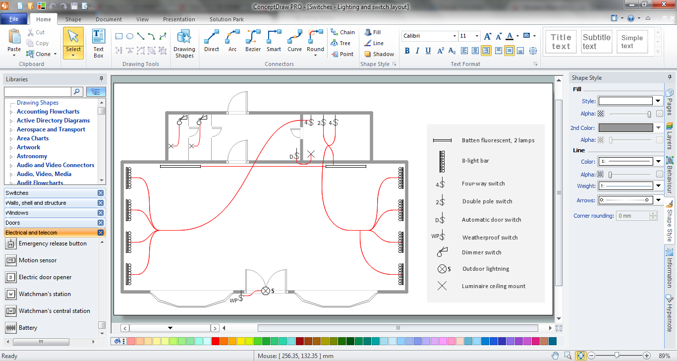
House Electrical Plan Software for creating great-looking home floor, electrical plan using professional electrical symbols.You can use many of built-in templates, electrical symbols and electical schemes examples of our House Electrical Diagram Software.
ConceptDraw is a fast way to draw: Electrical circuit diagrams, Schematics, Electrical Wiring, Circuit schematics, Digital circuits, Wiring in buildings, Electrical equipment, House electrical plans, Home cinema, Satellite television, Cable television, Closed-circuit television.
House Electrical Plan Software works across any platform, meaning you never have to worry about compatibility again. ConceptDraw DIAGRAM allows you to make electrical circuit diagrams on PC or macOS operating systems.

How To use Architect Software
Architect Software — Create electrical diagrams, architectural designs using ConceptDraw.
This cafe electrical floor plan sample shows the outlet and switch layout.
"An electrical drawing, is a type of technical drawing that shows information about power, lighting, and communication for an engineering or architectural project. Any electrical working drawing consists of "lines, symbols, dimensions, and notations to accurately convey an engineering's design to the workers, who install the electrical system on the job".
A complete set of working drawings for the average electrical system in large projects usually consists of:
(1) A plot plan showing the building's location and outside electrical wiring.
(2) Floor plans showing the location of electrical systems on every floor.
(3) Power-riser diagrams showing panel boards.
(4) Control wiring diagrams.
(5) Schedules and other information in combination with construction drawings.
Electrical drafters prepare wiring and layout diagrams used by workers who erect, install, and repair electrical equipment and wiring in communication centers, power plants, electrical distribution systems, and buildings." [Electrical drawing. Wikipedia]
The outlet and switch layout example "Cafe electrical floor plan" was created using the ConceptDraw PRO diagramming and vector drawing software extended with the Electric and Telecom Plans solution from the Building Plans area of ConceptDraw Solution Park.
The vector stencils library "Qualifying" contains 56 qualifying symbols of radiation, polarity, phase, windings, wire, ground, connection, connector, coaxial, electret.
Use these signs to annotate or specify characteristics of objects in electrical drawings, electronic schematics, circuit diagrams, electromechanical drawings, and wiring diagrams, cabling layout diagrams.
"An electrical drawing, is a type of technical drawing that shows information about power, lighting, and communication for an engineering or architectural project. Any electrical working drawing consists of "lines, symbols, dimensions, and notations to accurately convey an engineering's design to the workers, who install the electrical system on the job".
A complete set of working drawings for the average electrical system in large projects usually consists of:
(1) A plot plan showing the building's location and outside electrical wiring.
(2) Floor plans showing the location of electrical systems on every floor.
(3) Power-riser diagrams showing panel boards.
(4) Control wiring diagrams.
(5) Schedules and other information in combination with construction drawings.
Electrical drafters prepare wiring and layout diagrams used by workers who erect, install, and repair electrical equipment and wiring in communication centers, power plants, electrical distribution systems, and buildings." [Electrical drawing. Wikipedia]
The signs example "Design elements - Qualifying" was drawn using the ConceptDraw PRO diagramming and vector drawing software extended with the Electrical Engineering solution from the Engineering area of ConceptDraw Solution Park.
 Floor Plans
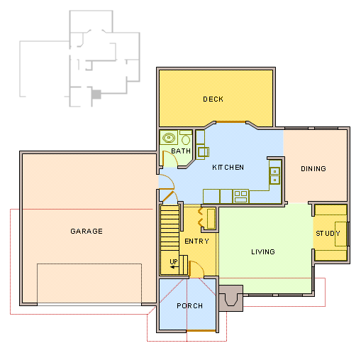
Construction, repair and remodeling of the home, flat, office, or any other building or premise begins with the development of detailed building plan and floor plans. Correct and quick visualization of the building ideas is important for further construction of any building.
How To use Appliances Symbols for Building Plan
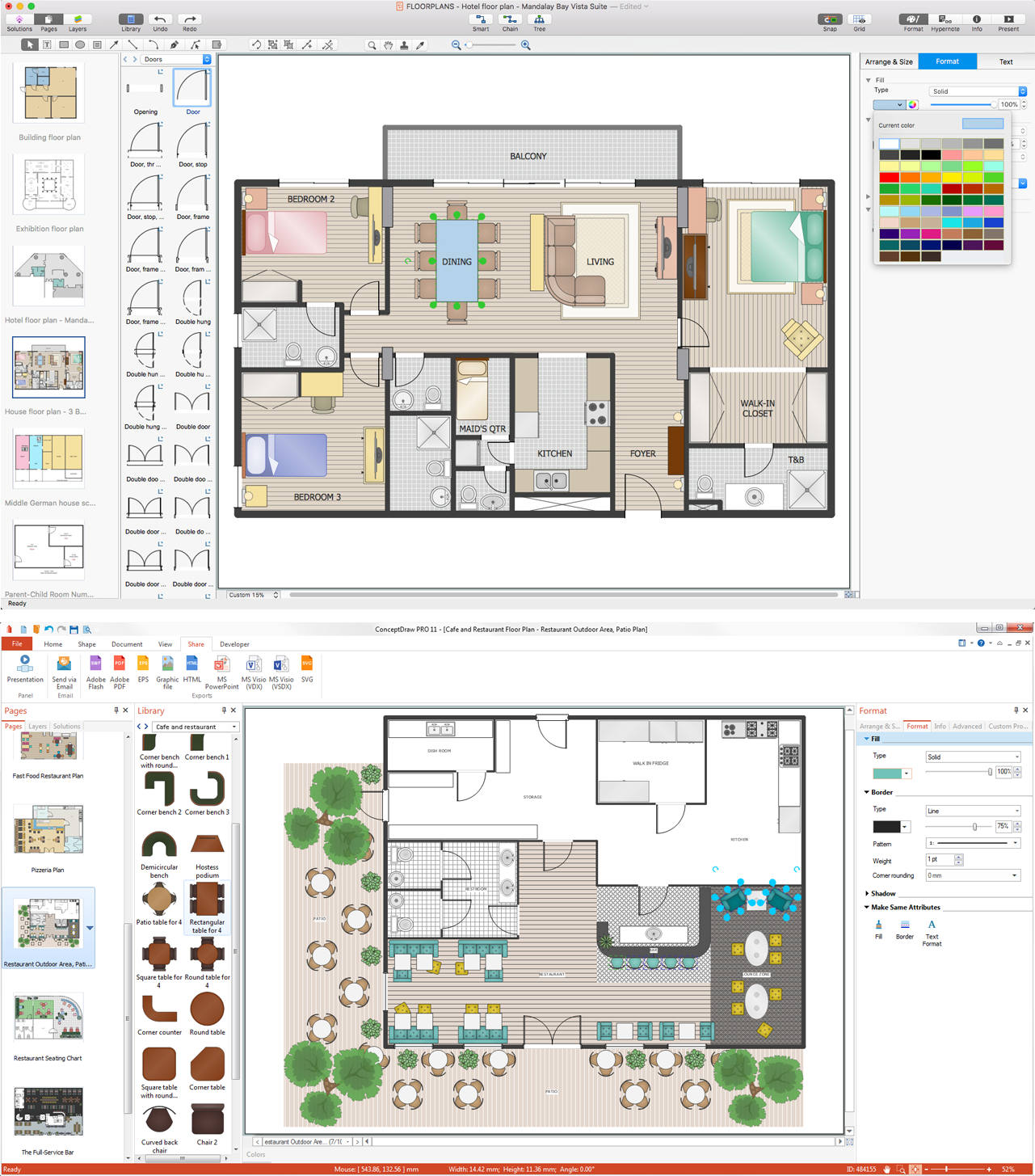
Having lots of design symbols for creating the floor plans for some house, cafe or office can be very helpful for making the great looking interior plan in a short period of time having our software ConceptDraw DIAGRAM as well as ConceptDraw STORE.CAD Drawing Software for Making Mechanic Diagram and Electrical Diagram Architectural Designs
CAD (Computer-aided design) software is used for improvement the quality of design and the productivity of the designer, for creating the database for manufacturing. Computer-aided design is used in many fields: in mechanical and industrial design, in designing electronic systems and electrical diagrams for architectural design, in automotive, aerospace, shipbuilding industries.
 Electric and Telecom Plans
The Electric and Telecom Plans solution providing the electric and telecom-related stencils, floor plan electrical symbols and pre-made examples is useful for electricians, interior designers, telecommunications managers, builders and other technicians when creating the electric visual plans and telecom drawings, home electrical plan, residential electric plan, telecom wireless plan, electrical floor plans whether as a part of the building plans or the independent ones.
Building Plan Software. Building Plan Examples
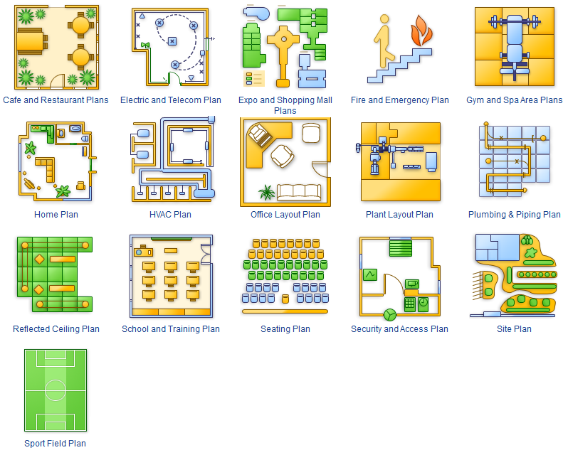
The Building Plans are very useful and even necessary for architects, builders, designers and simple for those who want to build the home, office, flat or anyone other building. They are also convenient for those who want to design or redesign the home, flat, room, etc.Fitness Plans
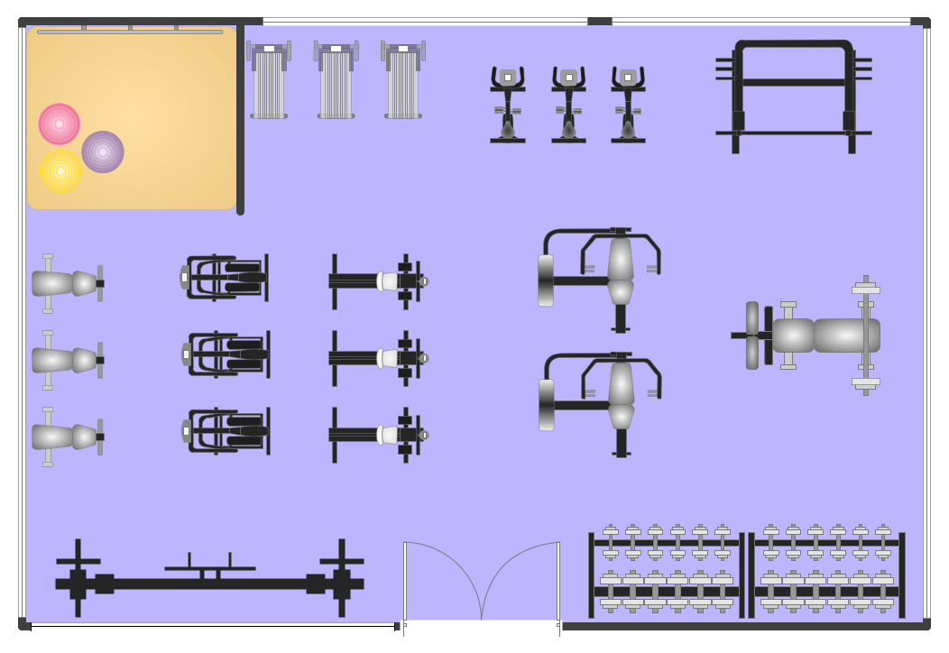
ConceptDraw DIAGRAM diagramming and vector drawing software extended with Gym and Spa Area Plans solution from Building Plans area of ConceptDraw Solution Park is the best for simple and fast drawing the Fitness Plans.How To Create Emergency Plans and Fire Evacuation
Once you start using ConceptDraw DIAGRAM all together with numerous libraries and templates of already existing, pre-designed plans, schemes, charts, flowcharts as well as diagrams, you will realize how simple and genius this application is.Building Drawing Software for Design Piping Plan
Use building drawing software to develop the annotated diagrams or schematics of waste water disposal systems, hot and cold water supply systems, water lines and waste water engineering.
Modern Garden Design
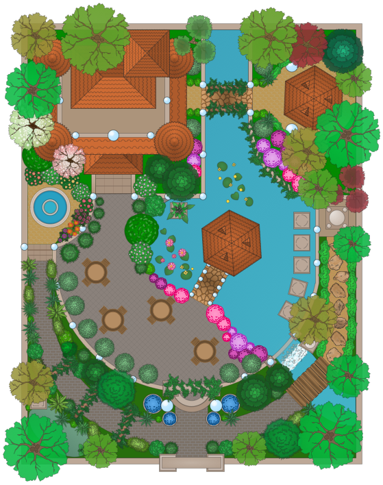
The modern garden design is a full complex of works for design, decorating and gardening. Landscape design offers a large number of styles for the modern garden design, their origins go back centuries. But do not forget that the modern garden design is first of all an individual project for a specific landscape and specific owner of the land, and sometimes it is appropriate to apply the combination of styles.ConceptDraw DIAGRAM diagramming and vector drawing software offers the unique Landscape & Garden Solution from the Building Plans area for effective development the modern garden design.
How To use Building Plan Examples
Whether you need to create the house floor plan, office floor plan or salon floor plan or other, you can always do it using our sophisticated software called ConceptDraw DIAGRAM with help of various libraries with many vector stencils to use for such schemes and plans.
Butterfly Network. Computer and Network Examples
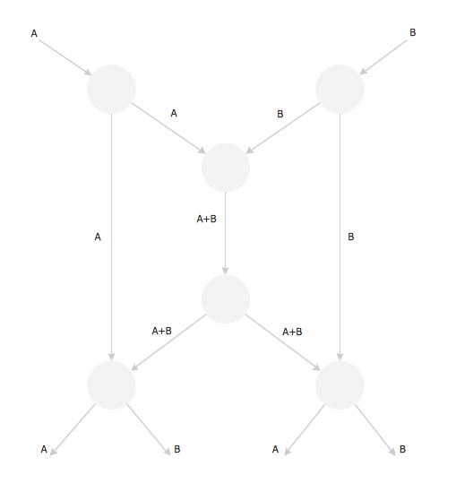
The Butterfly Network is the scheme that connects the units of a multiprocessing system and needs n stages to connect 2n processors. At the each stage the switch is thrown in depending of the particular bit in the addresses of the processors that are connected.
Telecom Wireless Plan
ConceptDraw DIAGRAM diagramming and vector drawing software extended with Electric and Telecom Plans Solution from the Building Plans Area is the best software for drawing the Telecom Wireless Plan of any complexity.How To use Electrical and Telecom Plan Software
When drawing Electrical and telecom plan, you need to display electrical circuit, schematics, electrical wiring, digital circuits and house electrical plans, etc. It shows the electrical devices location and the scheme of electric and telecom wiring clearly and concisely enough.For easy start, use Electric and Telecom plan solution templates and samples which will be opened right with standard electrical symbols and icons library. Or create your own electrical and telecom diagrams. Try now to make sure how easy and neat drawing electrical and telecom plan could be with ConceptDraw DIAGRAM!
Use Electrical and Telecom Plan Software to develop the home electrical plan, residential electric plan, telecom wireless plan, and other electric visual and telecommunication floor plans for design and construction, including outlets, switches, and fixtures.

 Network Layout Floor Plans
Network Layout Floor Plans solution extends ConceptDraw DIAGRAM software functionality with powerful tools for quick and efficient documentation the network equipment and displaying its location on the professionally designed Network Layout Floor Plans. Never before creation of Network Layout Floor Plans, Network Communication Plans, Network Topologies Plans and Network Topology Maps was not so easy, convenient and fast as with predesigned templates, samples, examples and comprehensive set of vector design elements included to the Network Layout Floor Plans solution. All listed types of plans will be a good support for the future correct cabling and installation of network equipment.
Electrical Symbols, Electrical Schematic Symbols
ConceptDraw DIAGRAM diagramming and vector drawing software enhanced with Electrical Engineering Solution from the Industrial Engineering Area of ConceptDraw Solution Park offers you powerful tools and libraries with incredibly large quantity of predesigned electrical symbols as electrical schematic symbols for easy designing professional looking Electrical Schematics.- Electrical Building Installation Layout And Wiring Diagram In Pdf
- Lay Out Building Electrical Installation Plan
- Symbols Of Electric Installation For Building
- Floor Plans For Electrical Building Installation For Electrical
- Prepare The Symbol Of Engineering Of Electrical Instaletion
- Electrical Installations Samples
- Building Electric Installation
- Bubble diagrams in Landscape Design with ConceptDraw DIAGRAM
- Office Layout Plans | Lighting and switch layout | Design Elements ...
- Building Electrical Installation Design Pdf
- Building Electrical Installation Design Pdf
- Electric and Telecom Plans | Design elements - Qualifying ...
- How Electric Installation In Building
- Classroom lighting - Reflected ceiling plan | Reflected ceiling plan ...
- Lighting and switch layout | Design elements - Electrical and ...
- Electric Installation Sample Drawing
- Electrical Diagram Installation
- Cafe electrical floor plan | Restaurant Floor Plan | How To Create ...
- HVAC Plans | Plant Layout Plans | Computer and Networks Area ...
- Architectural Engineering Symbol
- ERD | Entity Relationship Diagrams, ERD Software for Mac and Win
- Flowchart | Basic Flowchart Symbols and Meaning
- Flowchart | Flowchart Design - Symbols, Shapes, Stencils and Icons
- Flowchart | Flow Chart Symbols
- Electrical | Electrical Drawing - Wiring and Circuits Schematics
- Flowchart | Common Flowchart Symbols
- Flowchart | Common Flowchart Symbols


