Bank UML Diagram

 ATM UML Diagrams
The ATM UML Diagrams solution lets you create ATM solutions and UML examples. Use ConceptDraw DIAGRAM as a UML diagram creator to visualize a banking system.
Account Flowchart. Flowchart Examples
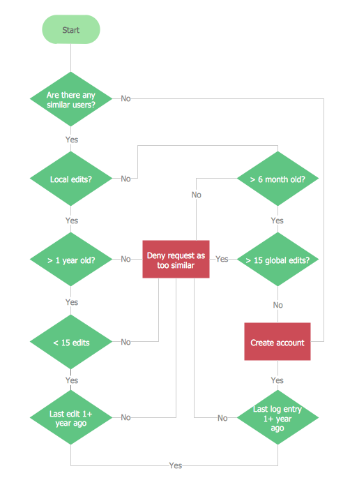
The flow chart example shows the computer network system account processing.
UML Use Case Diagram Example. Registration System

This sample was created in ConceptDraw DIAGRAM diagramming and vector drawing software using the UML Use Case Diagram library of the Rapid UML Solution from the Software Development area of ConceptDraw Solution Park.
This sample shows the types of user’s interactions with the system and is used at the registration and working with the database system.
How to create your UML Diagram

The 13 diagrams contained in the Rapid UML Solution offer an essential framework for systems analysts and software architects to create the diagrams they need to model processes from the conceptual level on through to project completion.
Bank System

Banking System

UML Use Case Diagram Example. Social Networking Sites Project

This sample shows the Facebook Socio-health system and is used at the projection and creating of the social networking sites.
Design Elements for UML Diagrams

SysML

ConceptDraw DIAGRAM diagramming and vector drawing software was extended with SysML Solution from the Software Development Area of ConceptDraw Solution Park specially to help systems engineers design various model systems with SysML.
UML Flowchart Symbols

The Rapid UML solution for ConceptDraw DIAGRAM software offers diversity of UML flowchart symbols for drawing all types of UML diagrams.
Introductory Guide to Rapid UML Solution

 Rapid UML
Rapid UML solution extends ConceptDraw DIAGRAM software with templates, samples and libraries of vector stencils for quick drawing the UML diagrams using Rapid Draw technology.
Personal area (PAN) networks. Computer and Network Examples
 networks")
This example was created in ConceptDraw DIAGRAM using the Computer and Networks Area of ConceptDraw Solution Park and shows the Personal area network.

Systems Engineering

ConceptDraw DIAGRAM supplied with SysML Solution from the Software Development Area of ConceptDraw Solution Park is a powerful and effective systems engineering software.
- Design elements - Bank UML profile diagram | Website user profile ...
- UML Use Case Diagram Example Social Networking Sites Project ...
- Example Of A User Profile Diagram
- Website user profile | Account Flowchart. Flowchart Examples | UML ...
- Flowchart For User Profile Settings
- Website user profile | Cloud clipart - Vector stencils library | IVR ...
- Sample Of A Bank User Profile Page
- SysML Diagram | HR workflow - Vector stencils library | Website user ...
- Entity Relationship Diagram For User Personal Profile
- Account Flowchart. Flowchart Examples | UML Use Case Diagram ...
- Account Flowchart. Flowchart Examples | UML Flowchart Symbols ...
- Flowchart Diagram To Manage Profile
- UML Use Case Diagram Example Social Networking Sites Project ...
- Sample Profile Of Atm Machine
- Personal area (PAN) networks. Computer and Network Examples ...
- Design elements - Bank UML profile diagram | Design elements ...
- Class UML Diagram for Bank Account System | Process Flowchart ...
- UML Use Case Diagram Example Social Networking Sites Project ...
- UML Use Case Diagram Example Social Networking Sites Project ...
- Profile Details Flowchart
- ERD | Entity Relationship Diagrams, ERD Software for Mac and Win
- Flowchart | Basic Flowchart Symbols and Meaning
- Flowchart | Flowchart Design - Symbols, Shapes, Stencils and Icons
- Flowchart | Flow Chart Symbols
- Electrical | Electrical Drawing - Wiring and Circuits Schematics
- Flowchart | Common Flowchart Symbols
- Flowchart | Common Flowchart Symbols