Entity Relationship Diagram Software Engineering

Professional ERD drawing is an essential software engineering method for database modeling. ConceptDraw DIAGRAM as a powerful Entity Relationship Diagram Software Engineering offers the tools of Entity-Relationship Diagram (ERD) solution from Software Development area of ConceptDraw Solution Park.
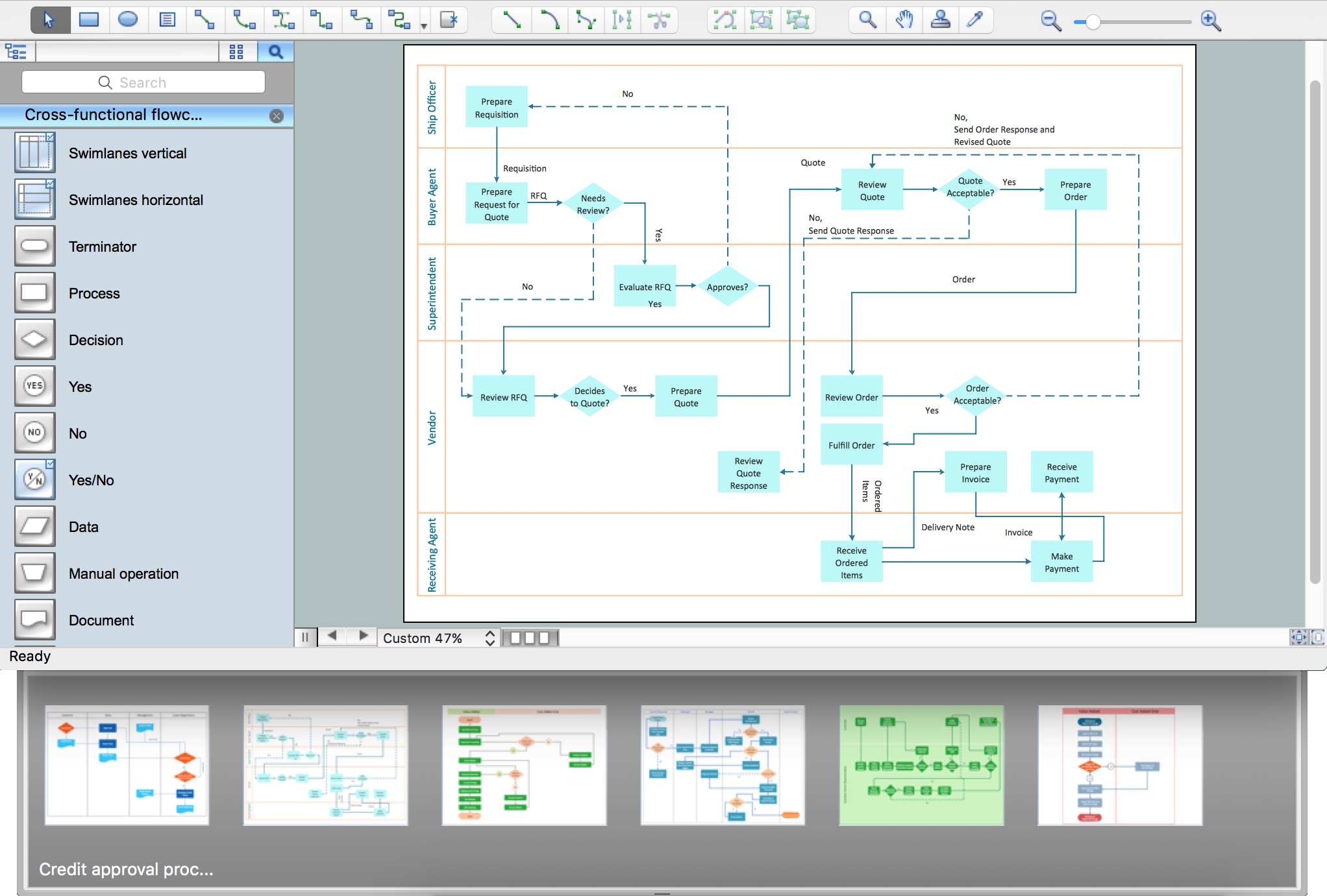
Process Flowchart

Data Flow Diagrams

UML Class Diagram Generalization Example UML Diagrams

This sample describes the use of the classes, the generalization associations between them, the multiplicity of associations and constraints. Provided UML diagram is one of the examples set that are part of Rapid UML solution.
UML Use Case Diagram Example Social Networking Sites Project
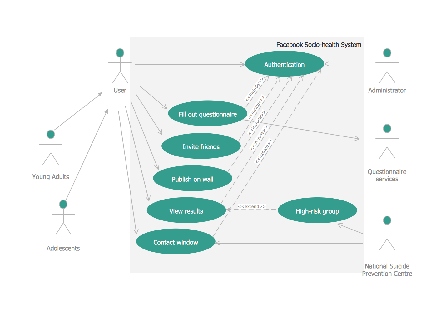
This sample shows the Facebook Socio-health system and is used at the projection and creating of the social networking sites.
Chemical Engineering

Program Structure Diagram
- College Management System Er Diagram In Dbms Pdf
- Er Diagram For College Database Management System
- Library Database Management System Er Diagram
- Entity-Relationship Diagram ( ERD ) | College Management System ...
- Draw College Database ER Diagram
- Er Diagram For Library Management System Of College
- Er Diagram For College Canteen Management System
- Simple Library Management System Database With Er Diagram In Pdf
- Entity-Relationship Diagram ( ERD ) | E R Daigram Of College Library
- Database Management System Er Diagram
- ERD | Entity Relationship Diagrams, ERD Software for Mac and Win
- Flowchart | Basic Flowchart Symbols and Meaning
- Flowchart | Flowchart Design - Symbols, Shapes, Stencils and Icons
- Flowchart | Flow Chart Symbols
- Electrical | Electrical Drawing - Wiring and Circuits Schematics
- Flowchart | Common Flowchart Symbols
- Flowchart | Common Flowchart Symbols