Mechanical Drawing Symbols

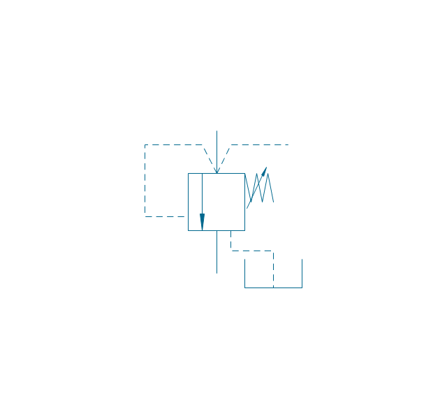
This example engineering drawing showing the hydraulic directional control valve usage with floating motor and pressure compensated pump is redesigned using the ConceptDraw PRO diagramming and vector drawing software from the Wikimedia Commons file: DCV 17.jpg.
[commons.wikimedia.org/ wiki/ File:DCV_ 17.jpg]
This file is licensed under the Creative Commons Attribution-Share Alike 3.0 Unported license.
[creativecommons.org/ licenses/ by-sa/ 3.0/ deed.en]
"Directional control valves are one of the most fundamental parts in hydraulic machinery as well and pneumatic machinery. They allow fluid flow into different paths from one or more sources. They usually consist of a spool inside a cylinder which is mechanically or electrically controlled. The movement of the spool restricts or permits the flow, thus it controls the fluid flow. ...
The spool (sliding type) consists of lands and grooves.The lands block oil flow through the valve body. The grooves allow oil or gas to flow around the spool and through the valve body. There are two fundamental positions of directional control valve namely normal position where valve returns on removal of actuating force and other is working position which is position of a valve when actuating force is applied. There is another class of valves with 3 or more position that can be spring centered with 2 working position and a normal position. ...
Directional control valves can be classified according to:
(1) number of ports;
(2) number of positions;
(3) actuating methods;
(4) type of spool." [Directional control valve. Wikipedia]
The fluid power equipment drawing example "Directional control valve" is included in the Mechanical Engineering solution from the Engineering area of ConceptDraw Solution Park.
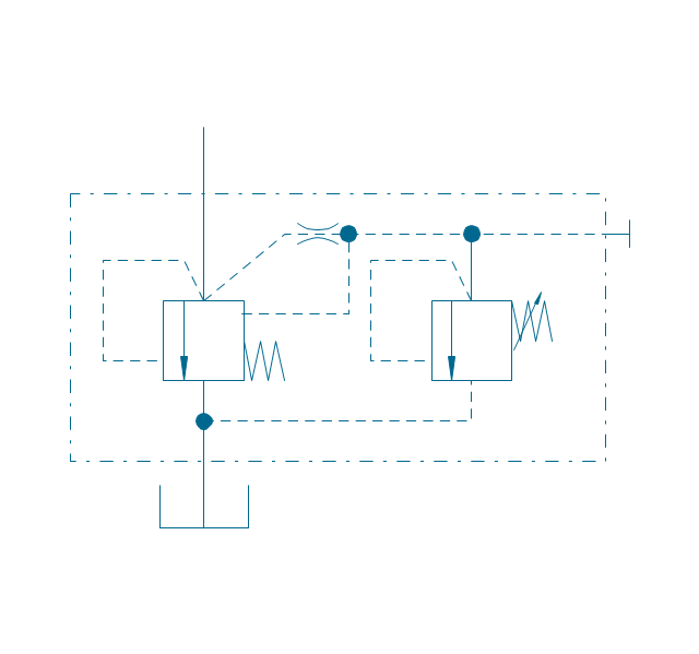
Hydraulic equipment schematic

"Directional control valves are one of the most fundamental parts in hydraulic machinery as well and pneumatic machinery. They allow fluid flow into different paths from one or more sources. They usually consist of a spool inside a cylinder which is mechanically or electrically controlled. The movement of the spool restricts or permits the flow, thus it controls the fluid flow." [Directional control valve. Wikipedia]
This example engineering drawing showing the directional control valve usage with fixed volume pump and hydraulic cylinder is redesigned using the ConceptDraw PRO diagramming and vector drawing software from Wikimedia Commons file: DCV 19.jpg.
[commons.wikimedia.org/ wiki/ File:DCV_ 19.jpg]
This file is licensed under the Creative Commons Attribution-Share Alike 3.0 Unported license.
[creativecommons.org/ licenses/ by-sa/ 3.0/ deed.en]
The fluid power equipment drawing example "Directional control valve" is included in the Mechanical Engineering solution from the Engineering area of ConceptDraw Solution Park.
Hydraulic equipment schematic

 Mechanical Engineering
This solution extends ConceptDraw DIAGRAM.9 mechanical drawing software (or later) with samples of mechanical drawing symbols, templates and libraries of design elements, for help when drafting mechanical engineering drawings, or parts, assembly, pneumatic,
The vector stencils library "Valve assembly" contains 141 symbols of pressure and flow regulators, flow direction indicators, controls, and symbols to design flow paths of control valves.
Use these valve assembly shapes to design the engineering drawings of hydraulic and pneumatic valve assemblies in fluid power systems.
"Control valves are valves used to control conditions such as flow, pressure, temperature, and liquid level by fully or partially opening or closing in response to signals received from controllers that compare a "setpoint" to a "process variable" whose value is provided by sensors that monitor changes in such conditions.
The opening or closing of control valves is usually done automatically by electrical, hydraulic or pneumatic actuators. Positioners are used to control the opening or closing of the actuator based on electric, or pneumatic signals.
A control valve consists of three main parts in which each part exist in several types and designs: Valve's actuator, Valve's positioner, Valve's body.
" [Control valves. Wikipedia]
The shapes example "" was created using the ConceptDraw PRO diagramming and vector drawing software extended with the Mechanical Engineering solution from the Engineering area of ConceptDraw Solution Park.
Valve assembly symbols

Mechanical Engineering

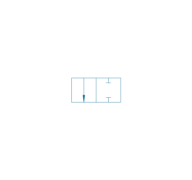
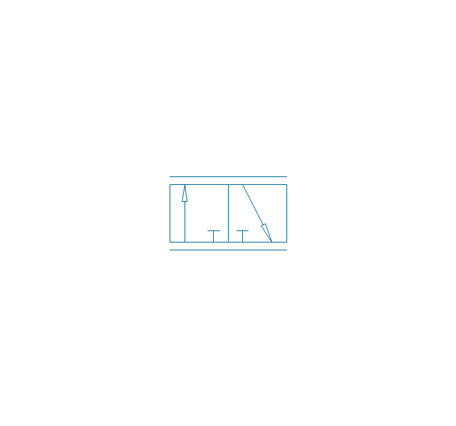
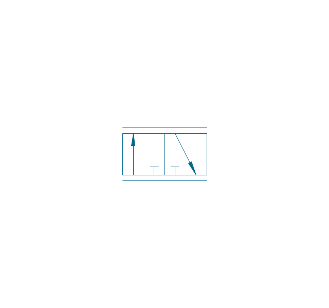
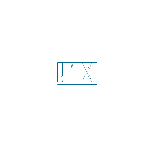
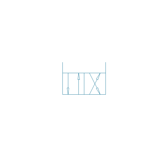
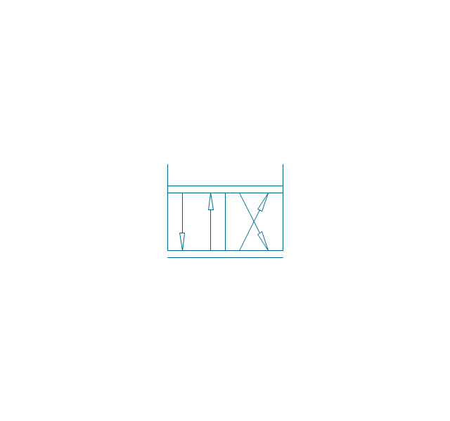
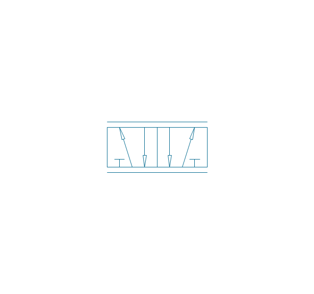
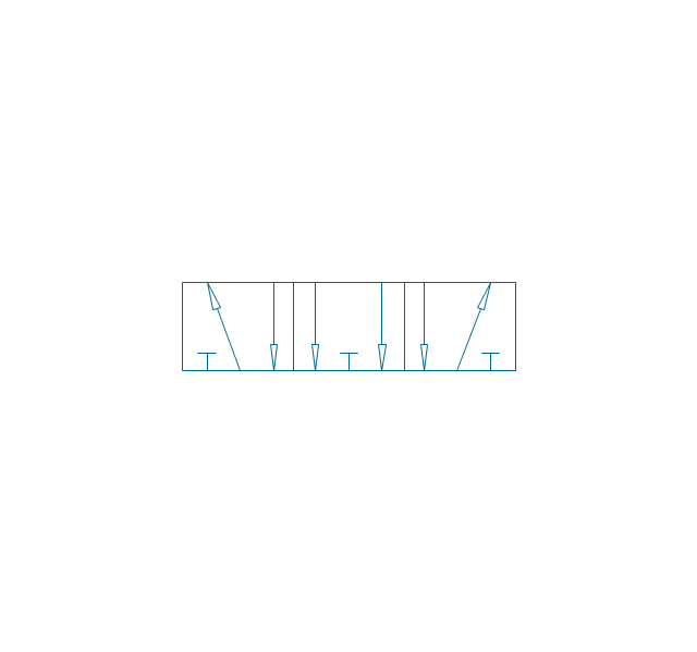
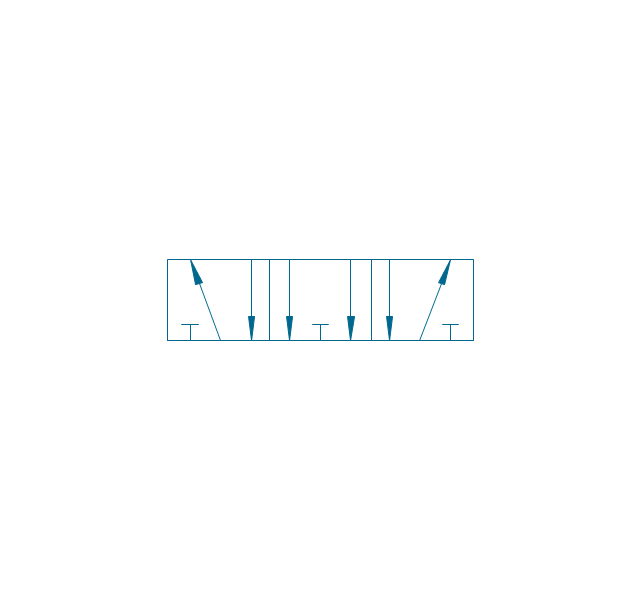
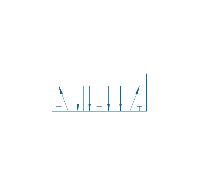
"Directional control valves are one of the most fundamental parts in hydraulic machinery as well and pneumatic machinery. They allow fluid flow into different paths from one or more sources. They usually consist of a spool inside a cylinder which is mechanically or electrically controlled. The movement of the spool restricts or permits the flow, thus it controls the fluid flow. ...
While working with layouts of hydraulic machinery it is cumbersome to draw actual picture of every valve and other components.instead of pictures symbols are used for variety of components in the hydraulic system to highlight the functional aspects. symbol for directional control valve is made of number of square boxes adjacent to each other depending on the number of positions.connections to the valve are shown on these squares by capital letters.usually they are named only in their normal position and not repeated in other positions.actuation system of the valve is also designated in its symbol." [Directional control valve. Wikipedia]
The Mac template "Pneumatic 5-ported 3-position valve" for the ConceptDraw PRO diagramming and vector drawing software is included in the Mechanical Engineering solution from the Engineering area of ConceptDraw Solution Park.
www.conceptdraw.com/ solution-park/ engineering-mechanical
Pneumatic directional control valve

Process Flow Diagram

ConceptDraw DIAGRAM diagramming and vector drawing software extended with powerful tools of Flowcharts Solution from the "Diagrams" Area of ConceptDraw Solution Park is effective for drawing: Process Flow Diagram, Flow Process Diagram, Business Process Flow Diagrams.
 Engineering
This solution extends ConceptDraw DIAGRAM.4 with the ability to visualize industrial systems in electronics, electrical, chemical, process, and mechanical engineering.
The vector stencils library "Fluid power valves" contains 93 symbols of pre-made hydraulic and pneumatic valves, including directional control valves, flow control valves, pressure control valves, and electrohydraulic and electropneumatic valves.
"Control valves are valves used to control conditions such as flow, pressure, temperature, and liquid level by fully or partially opening or closing in response to signals received from controllers that compare a "setpoint" to a "process variable" whose value is provided by sensors that monitor changes in such conditions.
The opening or closing of control valves is usually done automatically by electrical, hydraulic or pneumatic actuators. Positioners are used to control the opening or closing of the actuator based on electric, or pneumatic signals.
A control valve consists of three main parts in which each part exist in several types and designs: Valve's actuator, Valve's positioner, Valve's body.
" [Control valves. Wikipedia]
The shapes example "Design elements - Fluid power valves" was created using the ConceptDraw PRO diagramming and vector drawing software extended with the Mechanical Engineering solution from the Engineering area of ConceptDraw Solution Park.
Fluid power valve symbols

Retract resistor check valve application: pneumatic cylinder, piston driven by Compressed air through 2 Retract resistor check valves.
"A check valve, clack valve, non-return valve or one-way valve is a valve that normally allows fluid (liquid or gas) to flow through it in only one direction.
Check valves are two-port valves, meaning they have two openings in the body, one for fluid to enter and the other for fluid to leave. There are various types of check valves used in a wide variety of applications. Check valves are often part of common household items. Although they are available in a wide range of sizes and costs, check valves generally are very small, simple, or inexpensive. Check valves work automatically and most are not controlled by a person or any external control; accordingly, most do not have any valve handle or stem. The bodies (external shells) of most check valves are made of plastic or metal.
An important concept in check valves is the cracking pressure which is the minimum upstream pressure at which the valve will operate. Typically the check valve is designed for and can therefore be specified for a specific cracking pressure.
Heart valves are essentially inlet and outlet check valves for the heart ventricles, since the ventricles act as pumps." [Check valve. Wikipedia]
This hydraulic schematic example was redrawn using ConceptDraw PRO diagramming and vector drawing software from the Wikimedia Commons file: Retract resistor check valve application.png.
[commons.wikimedia.org/ wiki/ File:Retract_ resistor_ check_ valve_ application.png]
The hydraulic engineering drawing example "Retract resistor check valve application" was created using the ConceptDraw PRO diagramming and vector drawing software extended with the Mechanical Engineering solution from the Engineering area of ConceptDraw Solution Park.
Hydraulic schematic

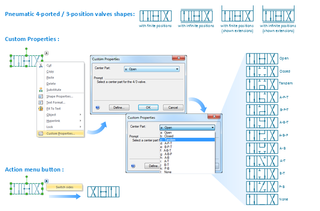
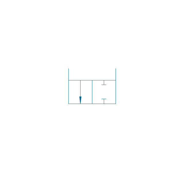
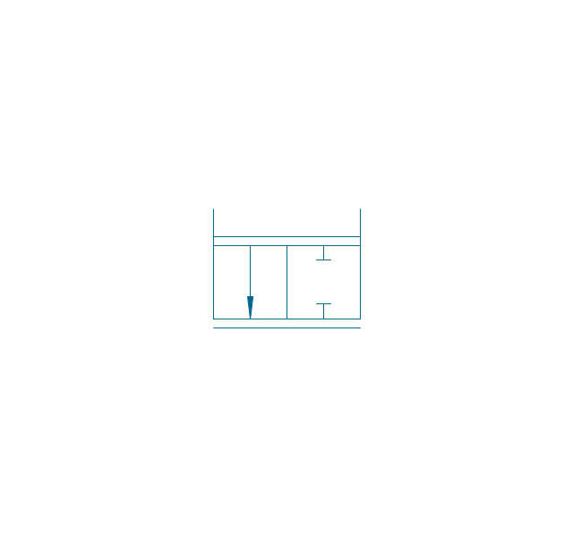
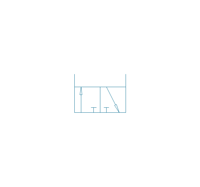
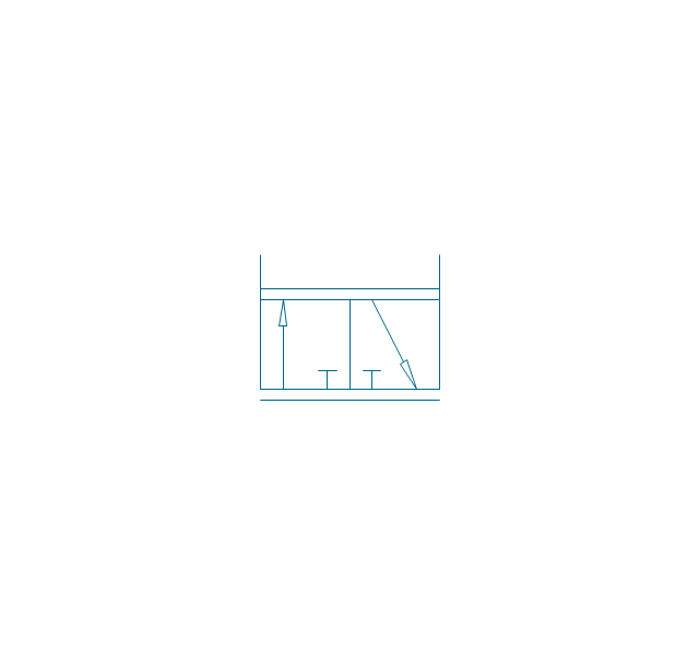
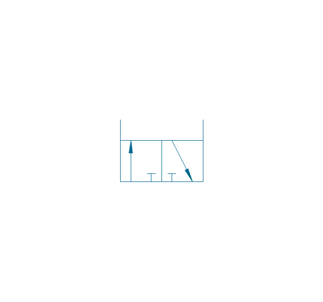
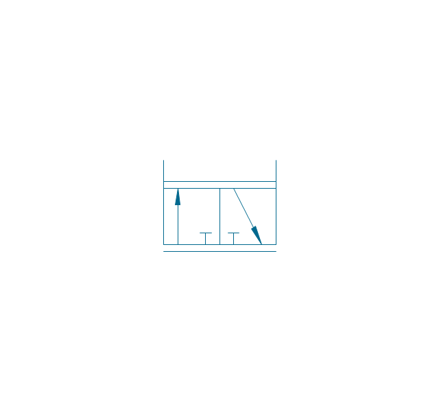
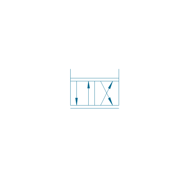
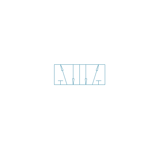
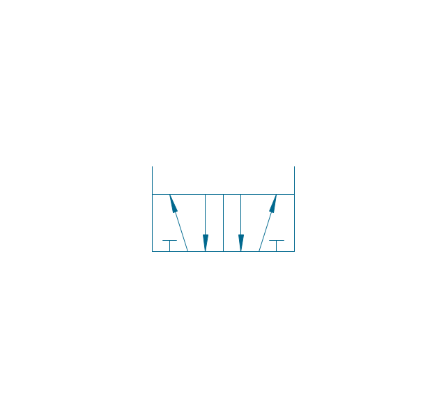
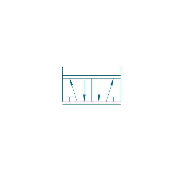
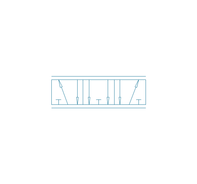
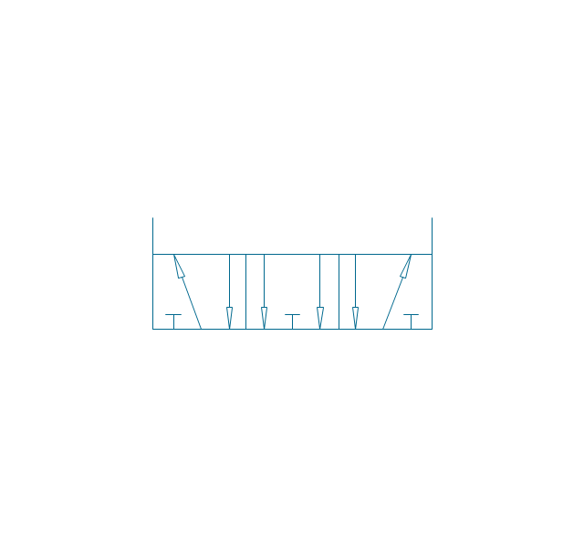
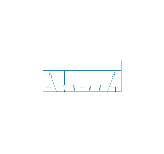
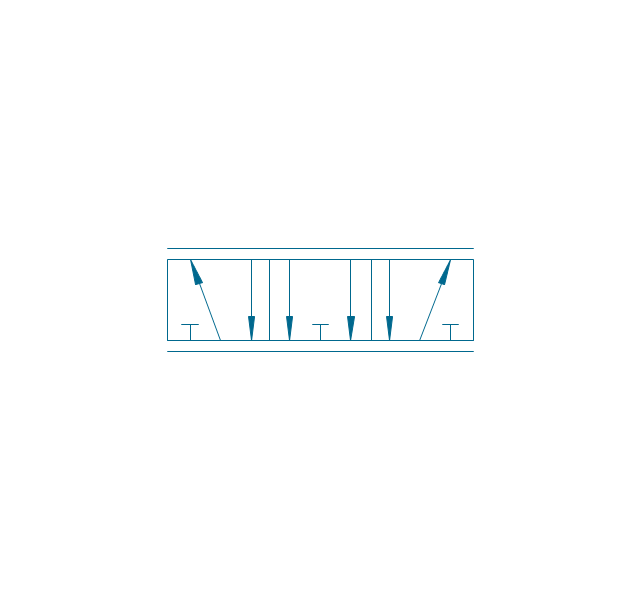
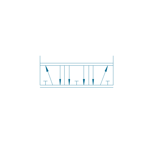
"An air-operated valve is a type of power operated valve that uses air pressure against a piston or diaphragm to produce linear or circular movement to operate a valve. Types are 2-way, 3-way and 4-way. The 2 way air-operated valves can be either normally closed or normally opened." [Air-operated valve. Wikipedia]
The Windows template "Pneumatic 4-ported 3-position valve" for the ConceptDraw PRO diagramming and vector drawing software is included in the Mechanical Engineering solution from the Engineering area of ConceptDraw Solution Park.
www.conceptdraw.com/ solution-park/ engineering-mechanical
The Windows template "Pneumatic 4-ported 3-position valve" for the ConceptDraw PRO diagramming and vector drawing software is included in the Mechanical Engineering solution from the Engineering area of ConceptDraw Solution Park.
www.conceptdraw.com/ solution-park/ engineering-mechanical
Pneumatic directional control valve
Process Flow Diagram Symbols

The vector stencils library "Fluid power valves" contains 93 symbols of pre-made hydraulic and pneumatic valves, including directional control valves, flow control valves, pressure control valves, and electrohydraulic and electropneumatic valves.
Use these shapes to design fluid power diagrams in the ConceptDraw PRO diagramming and vector drawing software extended with the Mechanical Engineering solution from the Engineering area of ConceptDraw Solution Park.
www.conceptdraw.com/ solution-park/ engineering-mechanical
Use these shapes to design fluid power diagrams in the ConceptDraw PRO diagramming and vector drawing software extended with the Mechanical Engineering solution from the Engineering area of ConceptDraw Solution Park.
www.conceptdraw.com/ solution-park/ engineering-mechanical
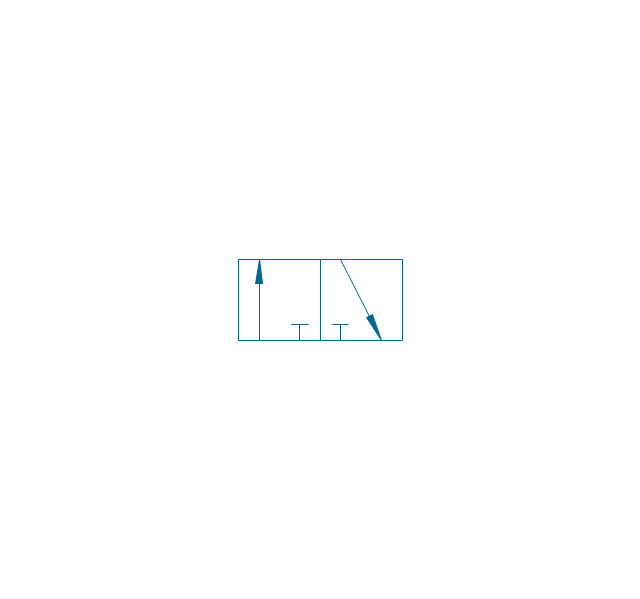
2/2 valve, pneum., finite positions

2/2 valve, pneum., infinite positions
2/2 valve, pneum., ext., fin. pos.
2/2 valve, pneum., ext., infin. pos.
2/2 valve, hydr., finite positions
2/2 valve, hydr., infinite positions

2/2 valve, hydr., ext., fin. pos.
2/2 valve, hydr., ext., infin. pos.
3/2 valve, pneum., finite positions
3/2 valve, pneum., infinite positions
3/2 valve, pneum., ext., fin. pos.
3/2 valve, pneum., ext., infin. pos.
3/2 valve, hydr., finite positions
3/2 valve, hydr., infinite positions
3/2 valve, hydr., ext., fin. pos.
3/2 valve, hydr., ext., infin. pos.
4/2 valve, pneum., finite positions

4/2 valve, pneum., infinite positions
4/2 valve, pneum., ext., fin. pos.
4/2 valve, pneum., ext., infin. pos.
4/2 valve, hydr., finite positions

4/2 valve, hydr., infinite positions

4/2 valve, hydr., ext., fin. pos.

4/2 valve, hydr., ext., infin. pos.
5/2 valve, pneum., finite positions
5/2 valve, pneum., infinite positions
5/2 valve, pneum., ext., fin. pos.

5/2 valve, pneum., ext., infin. pos.

5/2 valve, hydr., finite positions

5/2 valve, hydr., infinite positions

5/2 valve, hydr., ext., fin. pos.
5/2 valve, hydr., ext., infin. pos.
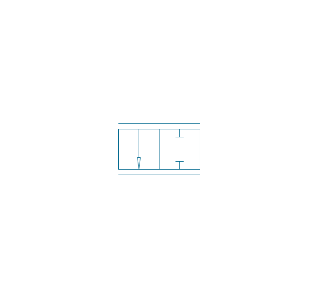
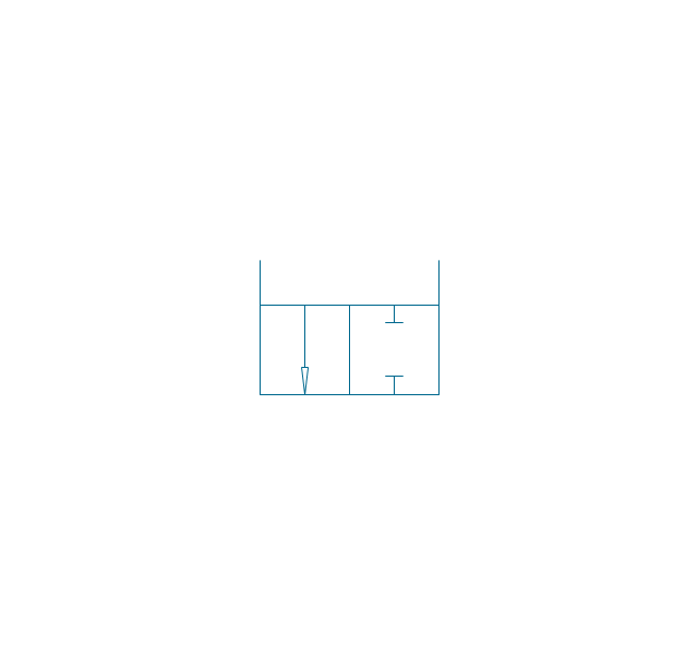
4/3 valve, pneum., finite positions

4/3 valve, pneum., infinite positions

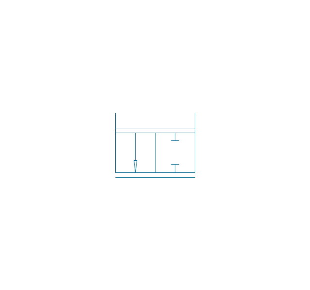
4/3 valve, pneum., ext., fin. pos.

4/3 valve, pneum., ext., infin. pos.
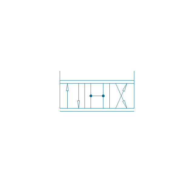
4/3 valve, hydr., finite positions

4/3 valve, hydr., infinite positions

4/3 valve, hydr., ext., fin. pos.

4/3 valve, hydr., ext., infin. pos.

5/3 valve, pneum., finite positions
5/3 valve, pneum., infinite positions
5/3 valve, pneum., ext., fin. pos.
5/3 valve, pneum., ext., infin. pos.
5/3 valve, hydr., finite positions
5/3 valve, hydr., infinite positions
5/3 valve, hydr., ext., fin. pos.
5/3 valve, hydr., ext., infin. pos.
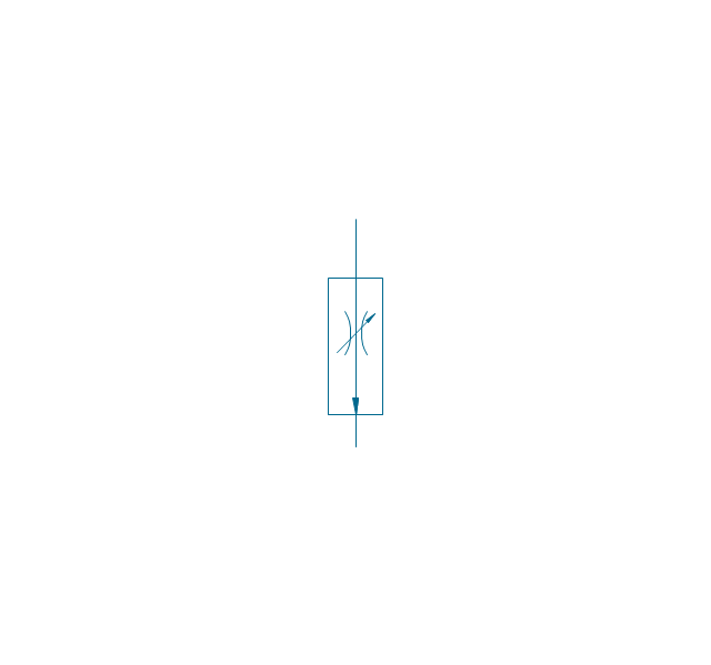
Restrictor valve

Restrictor valve, adjustable
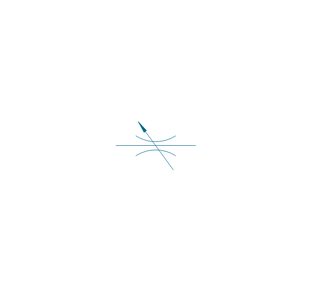
Gate-valve, norm. open
Gate-valve, norm. open, adj.
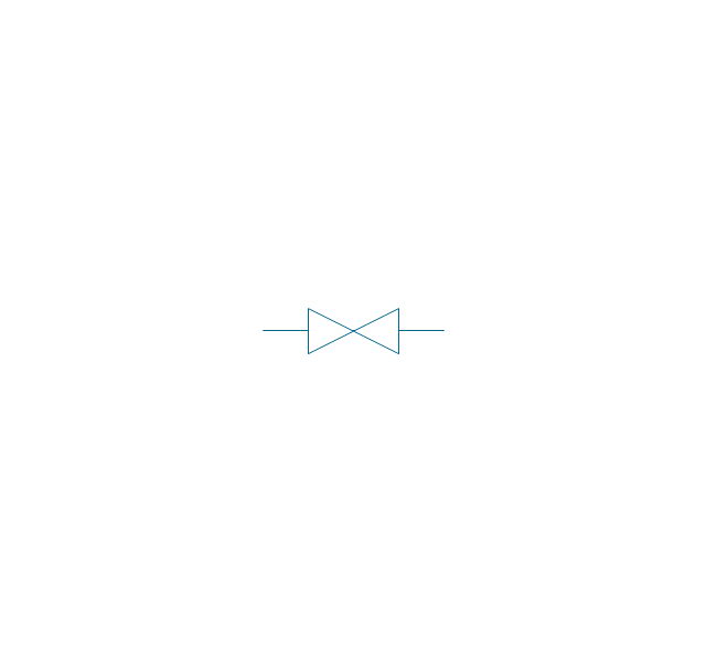
Gate-valve, norm. closed

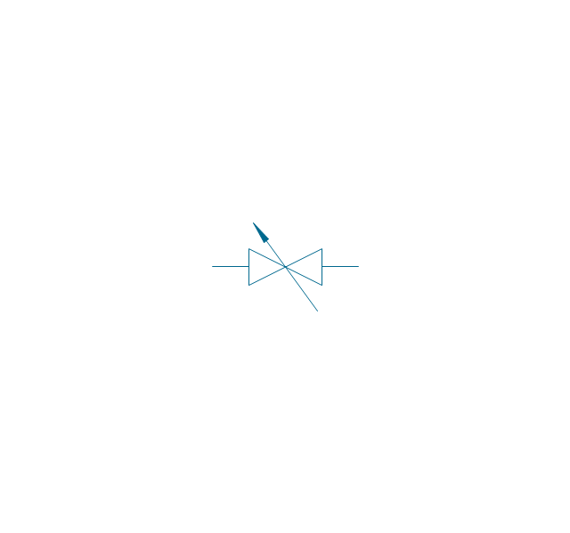
Gate-valve, norm. closed, adj.

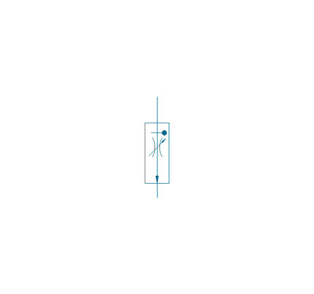
One-way restrictor
One-way restrictor, enclosed
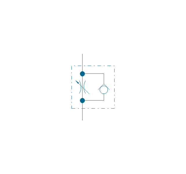
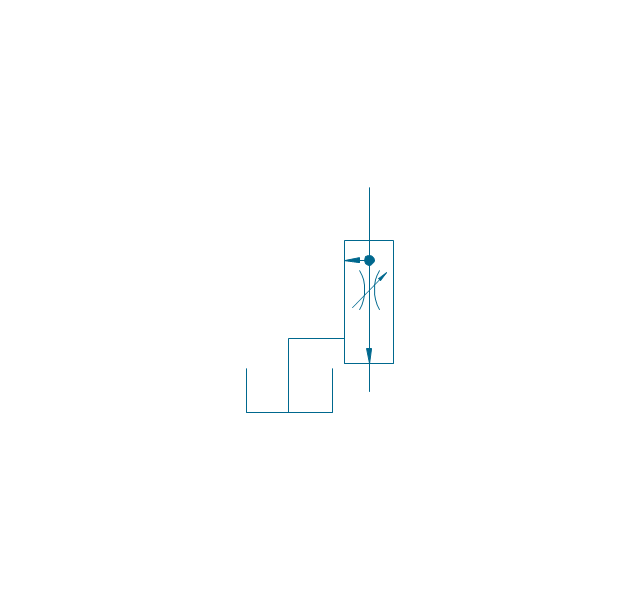
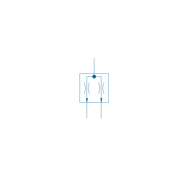
Flow control, series flow
Flow control, temperature compensated
Flow control, bypass flow
Flow divider
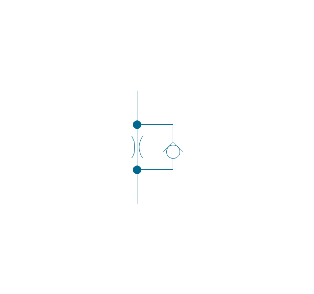
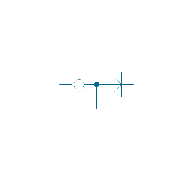
Non-return, pilot controlled
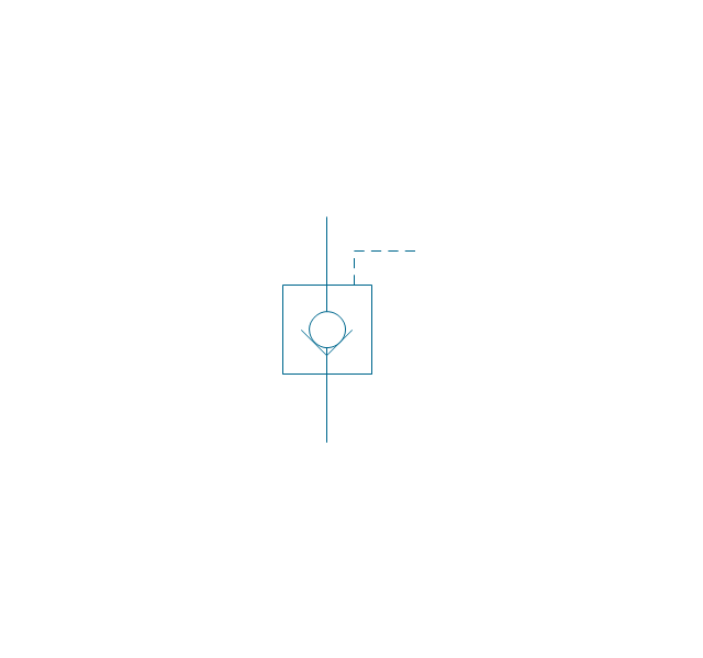
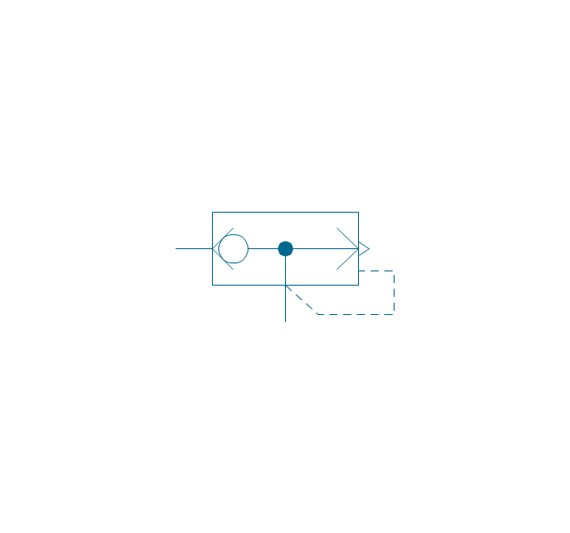
Non-return, pilot contr., spring
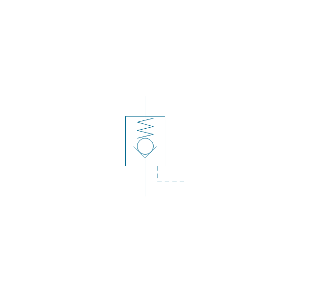
Non-return, free
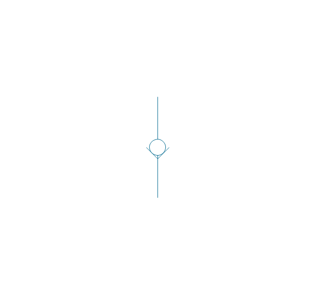
Non-return, spring loaded
Coupling (connect.), 1 valve
,-1-valve-fluid-power-valves---vector-stencils-library.png--diagram-flowchart-example.png)
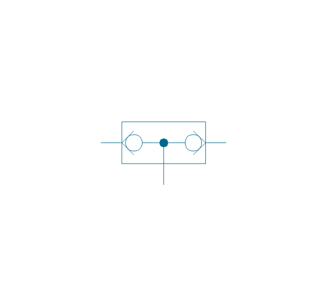
Coupling (connect.), both valves
,-both-valves-fluid-power-valves---vector-stencils-library.png--diagram-flowchart-example.png)
Coupling (connect.), no valves
,-no-valves-fluid-power-valves---vector-stencils-library.png--diagram-flowchart-example.png)
Coupling (connect.), 1 valve, encl.
,-1-valve,-encl.-fluid-power-valves---vector-stencils-library.png--diagram-flowchart-example.png)
Coupling (connect.), both valves, encl.
,-both-valves,-encl.-fluid-power-valves---vector-stencils-library.png--diagram-flowchart-example.png)
Coupling (connect.), no valves, encl.
,-no-valves,-encl.-fluid-power-valves---vector-stencils-library.png--diagram-flowchart-example.png)
Coupling (discon.), 1 valve
,-1-valve-fluid-power-valves---vector-stencils-library.png--diagram-flowchart-example.png)
Coupling (discon.), both valves
,-both-valves-fluid-power-valves---vector-stencils-library.png--diagram-flowchart-example.png)
Coupling (discon.), no valves
,-no-valves-fluid-power-valves---vector-stencils-library.png--diagram-flowchart-example.png)
Coupling (discon.), 1 valve, encl.
,-1-valve,-encl.-fluid-power-valves---vector-stencils-library.png--diagram-flowchart-example.png)
Coupling (discon.), both valves, encl.
,-both-valves,-encl.-fluid-power-valves---vector-stencils-library.png--diagram-flowchart-example.png)
Coupling (discon.), no valves, encl.
,-no-valves,-encl.-fluid-power-valves---vector-stencils-library.png--diagram-flowchart-example.png)
Shuttle valve
Priority shuttle valve
Quick exhaust
Cartridge valve
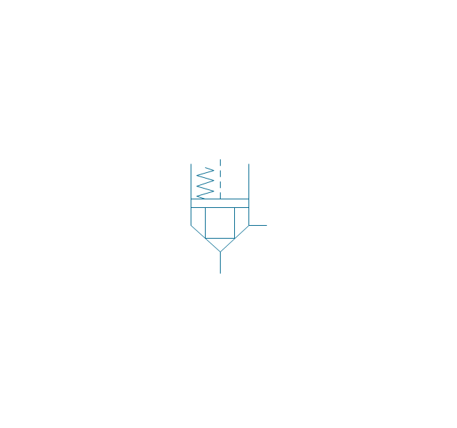
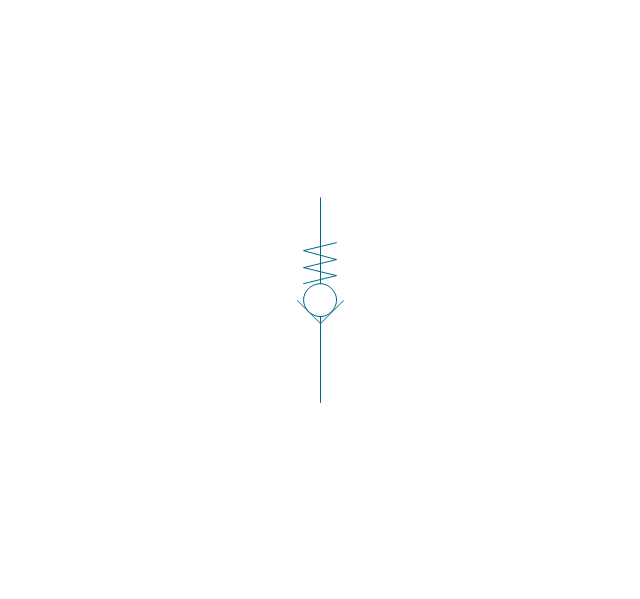
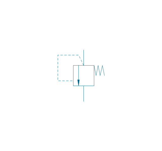
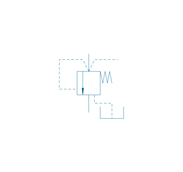
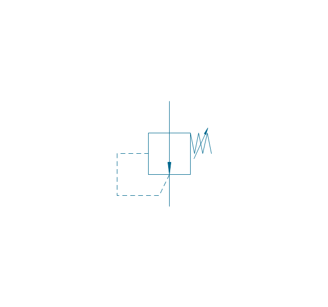
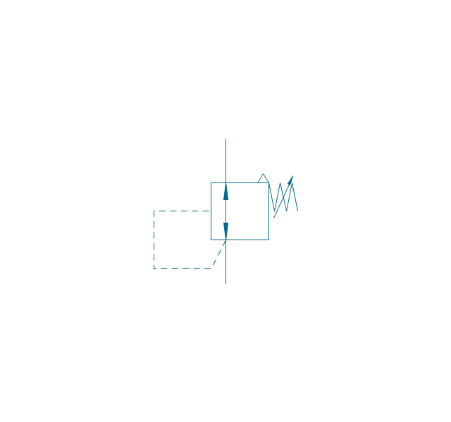
Pressure relief
Pressure relief, drain
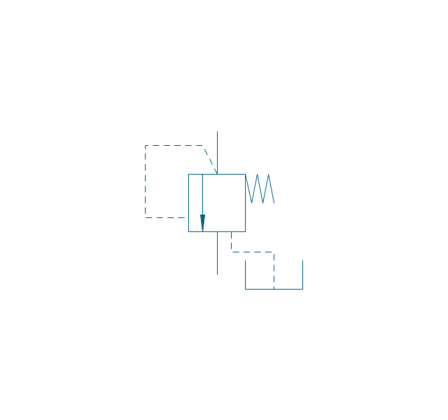
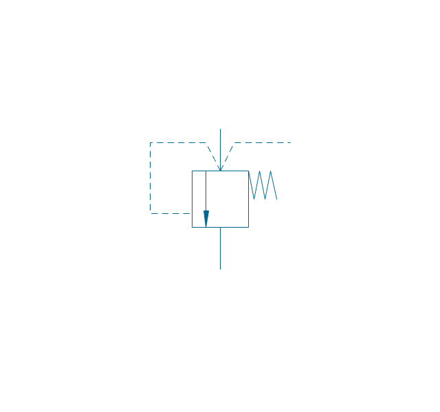
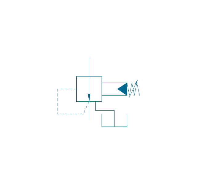
Pressure relief, vent port
Pressure relief, drain, vent port
Pressure relief, var.
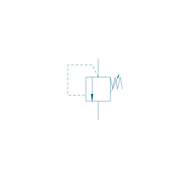
Pressure relief, var., drain
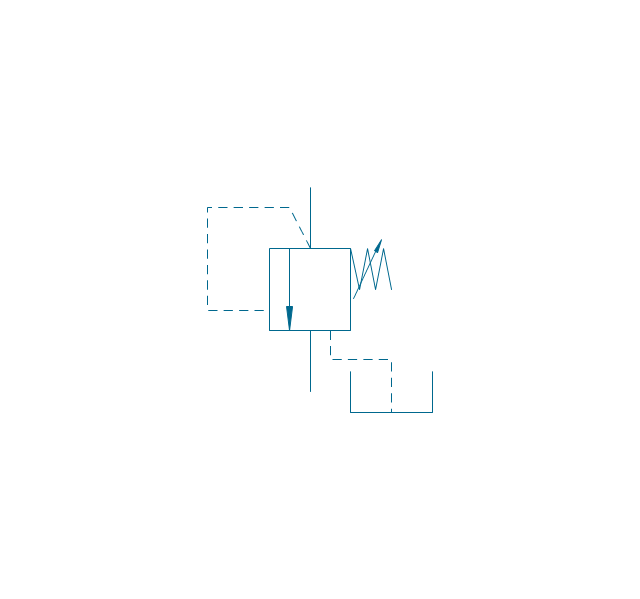
Pressure relief, var., vent port
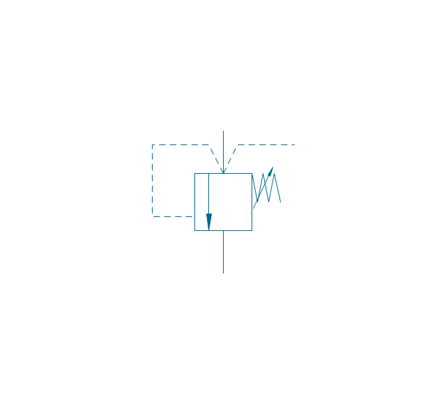
Pressure relief, var., drain, vent port
Pressure relief 2
Pressure reducing, 1 stage
Pressure reducing, 2 stage
Pressure reducing, relief
Pressure relief (E)
-fluid-power-valves---vector-stencils-library.png--diagram-flowchart-example.png)
Process Flow Chart

ConceptDraw DIAGRAM diagramming and vector drawing software extended with Flowcharts Solution from the "Diagrams" Area of ConceptDraw Solution Park is the best way to create Process Flow Chart and other types of flowcharts.
- Valve Engineering Drawing
- Engineering Drawing Of Control Valve
- Directional control valve
- Mechanical Drawing Symbols | Directional control valve ...
- Water Flow Control Valve Engineering Drawing With Assembly And
- A Valve Pump Engineering Drawing
- Technical drawing - Machine parts assembling | Mechanical ...
- Valves Engineering Drawing
- Flow Control Valve Line Diagram
- Directional control valve | Mechanical Drawing Symbols | Directional ...
- Mechanical Engineering | Mechanical Drawing Symbols ...
- Control Valve Engineering Drawings Detailing
- Mechanical Engineering | Mechanical Drawing Software ...
- Mechanical Drawing Symbols | Mechanical Engineering ...
- Pneumatic Control Valve Piping Diagram
- Flow Control Valve Symbol
- Mechanical Drawing Symbols | Directional control valve | Design ...
- Hydraulic schematic | Directional control valve | Directional control ...
- Mechanical Drawing Software | Directional control valve | Pneumatic ...
- Mechanical Drawing Symbols | Design elements - Valve assembly ...
- ERD | Entity Relationship Diagrams, ERD Software for Mac and Win
- Flowchart | Basic Flowchart Symbols and Meaning
- Flowchart | Flowchart Design - Symbols, Shapes, Stencils and Icons
- Flowchart | Flow Chart Symbols
- Electrical | Electrical Drawing - Wiring and Circuits Schematics
- Flowchart | Common Flowchart Symbols
- Flowchart | Common Flowchart Symbols