Electrical Symbols, Electrical Diagram Symbols

This solution provides 26 libraries which contain 926 electrical symbols from electrical engineering: Analog and Digital Logic, Composite Assemblies, Delay Elements, Electrical Circuits, Electron Tubes, IGFET, Inductors, Integrated Circuit, Lamps, Acoustics, Readouts, Logic Gate Diagram, MOSFET, Maintenance, Power Sources, Qualifying, Resistors, Rotating Equipment, Semiconductor Diodes, Semiconductors, Stations, Switches and Relays, Terminals and Connectors, Thermo, Transformers and Windings, Transistors, Transmission Paths,VHF UHF SHF.
CAD Drawing Software for Making Mechanic Diagram and Electrical Diagram Architectural Designs


Electrical Design Software

Mechanical Drawing Symbols

Block Diagram Creator

Electrical Diagram Software

Electrical Engineering Solution for ConceptDraw DIAGRAM provides the 26 stencils libraries of ready-to-use predesigned vector symbols, templates and samples that make your electrical drawing quick, easy and effective.
Circuits and Logic Diagram Software

Electrical Engineering solution helps you create quick and easy: Electrical schematics, Digital and analog logic designs, Circuit and wiring schematics and diagrams, Power systems diagrams, Maintenance and repair diagrams, Circuit board and amplifier diagrams, Integrated circuit schematics.
Mechanical Design Software

Building Drawing. Design Element Site Plan

Use Site Plan symbols to draw your own residential and commercial landscape design, parks planning, yard layouts, plat maps, outdoor recreational facilities, and irrigation systems.

Basic Diagramming


CAD Software for Architectural Designs
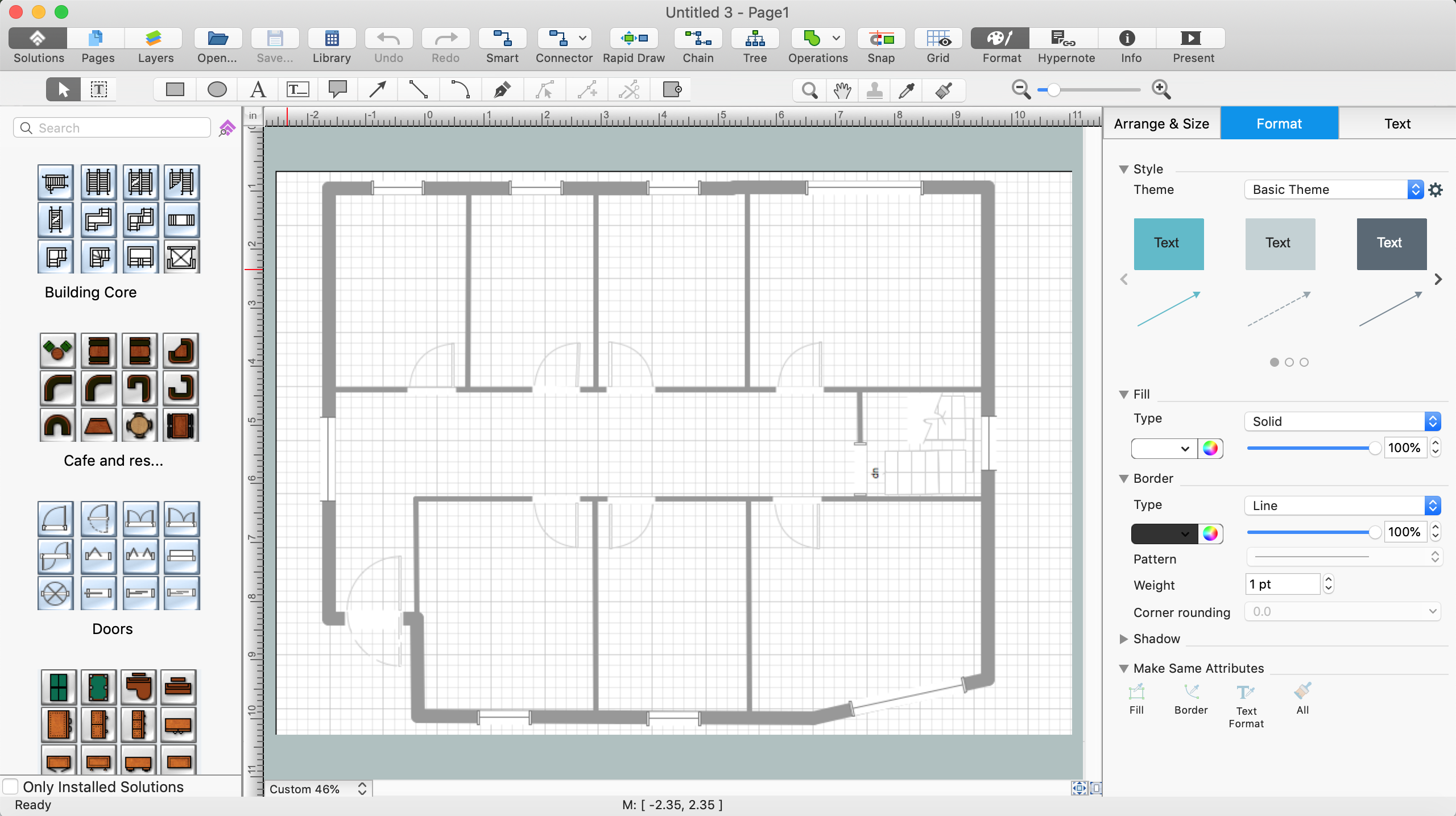
ConceptDraw DIAGRAM diagramming and vector drawing software allows you the possibility to draw your architectural designs quick, simple and effective.
Use the libraries with a set of vector objects, templates and samples from the Floor Plans Solution from the Building Plans area of ConceptDraw Solution Park for designing your professional architectural designs.
Sign Making Software

Sign making software is very useful tool for professional sign-making business. Use ConceptDraw DIAGRAM and make sure that now sign making is easier and timesaving than ever!
Interior Design. Office Layout Plan Design Element

ConceptDraw Building Drawing Tools - draw simple office layout plans easily with Office Layout Plan Design Element. Use it to draw office interior design floor plans, office furniture and equipment layouts, and blueprints for facilities management, move management, office supply inventories, assets inventories, office space planning.
Process Flow Diagram

ConceptDraw DIAGRAM diagramming and vector drawing software extended with powerful tools of Flowcharts Solution from the "Diagrams" Area of ConceptDraw Solution Park is effective for drawing: Process Flow Diagram, Flow Process Diagram, Business Process Flow Diagrams.
- Engineering Drawing Electronic Mechanics Pdf
- Mechanical Engineering Drawing Symbol In Pdf Of Industries
- CAD Drawing Software for Making Mechanic Diagram and Electrical
- CAD Drawing Software for Making Mechanic Diagram and Electrical ...
- CAD Drawing Software for Making Mechanic Diagram and Electrical ...
- Electronics Engineering Drawing Diagram
- CAD Drawing Software for Making Mechanic Diagram and Electrical
- Advanced Technical Drawing Diagrams Pdf
- Electrical And Electronic Engineering Solution To Circult Diagrams Pdf
- Making Mechanical Diagram | Electrical Symbols, Electrical Diagram ...
- Technical Drawing Software | Chemical Engineering | Engineering ...
- Electrical Electronics Drawing Pdf
- Automobile Engineering Drawing Symbols In Pdf File
- Engineering | Technical Drawing Software | Electrical Drawing ...
- Architectural Drawing Pdf
- CAD Drawing Software for Making Mechanic Diagram and Electrical ...
- Mechanical Engineering Drawing Symbols Pdf Free Download
- Technical Drawing Software | Electrical Drawing Software and ...
- Mechanical Drawing Symbols | Mechanical Design Software ...
- Electrical Engineer Drawing Pdf File Free Download
- ERD | Entity Relationship Diagrams, ERD Software for Mac and Win
- Flowchart | Basic Flowchart Symbols and Meaning
- Flowchart | Flowchart Design - Symbols, Shapes, Stencils and Icons
- Flowchart | Flow Chart Symbols
- Electrical | Electrical Drawing - Wiring and Circuits Schematics
- Flowchart | Common Flowchart Symbols
- Flowchart | Common Flowchart Symbols